Microscope
a microscope and microscope technology, applied in the field of microscopes, can solve the problem of not being able to dye a living body desirabl
- Summary
- Abstract
- Description
- Claims
- Application Information
AI Technical Summary
Benefits of technology
Problems solved by technology
Method used
Image
Examples
first embodiment
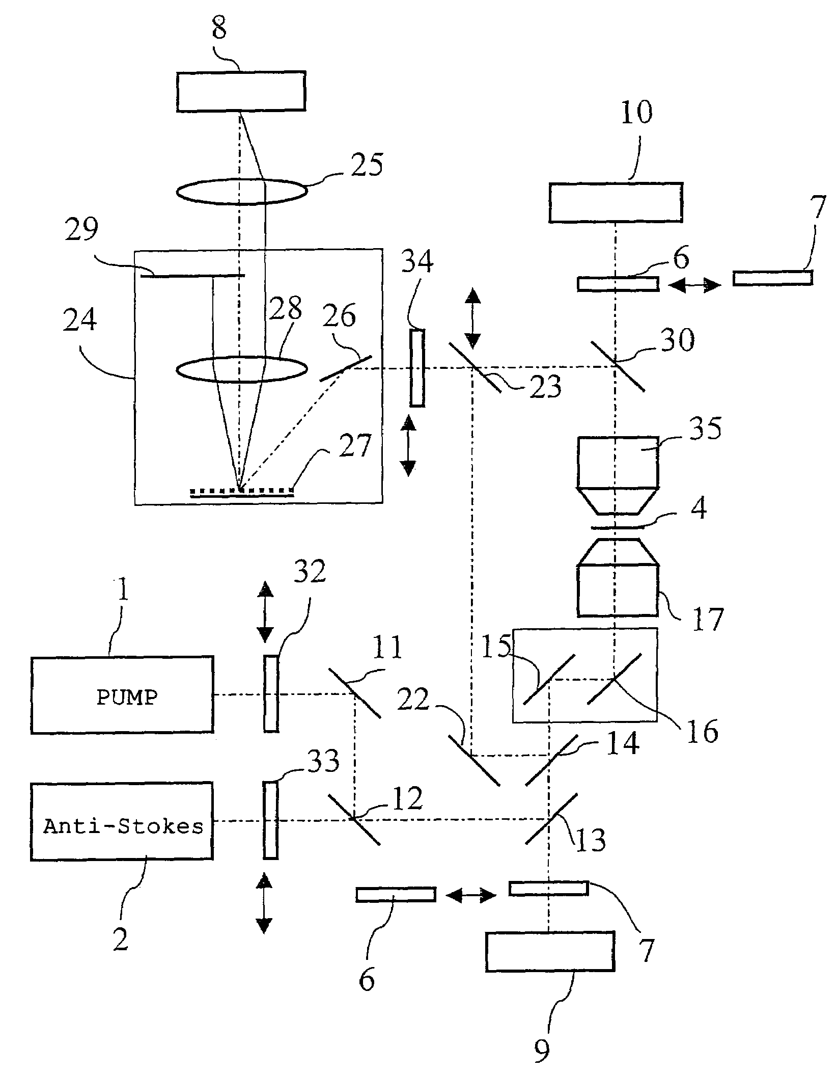
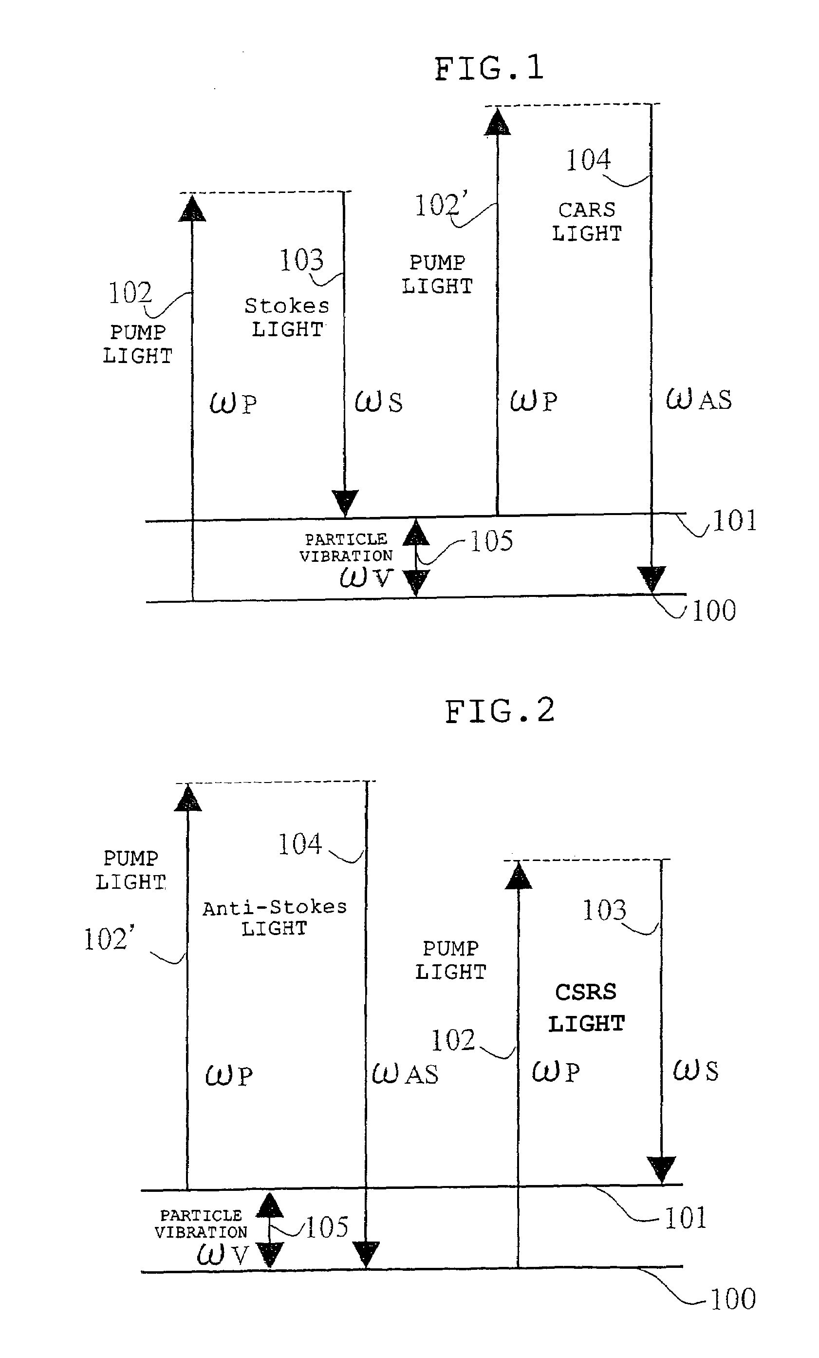
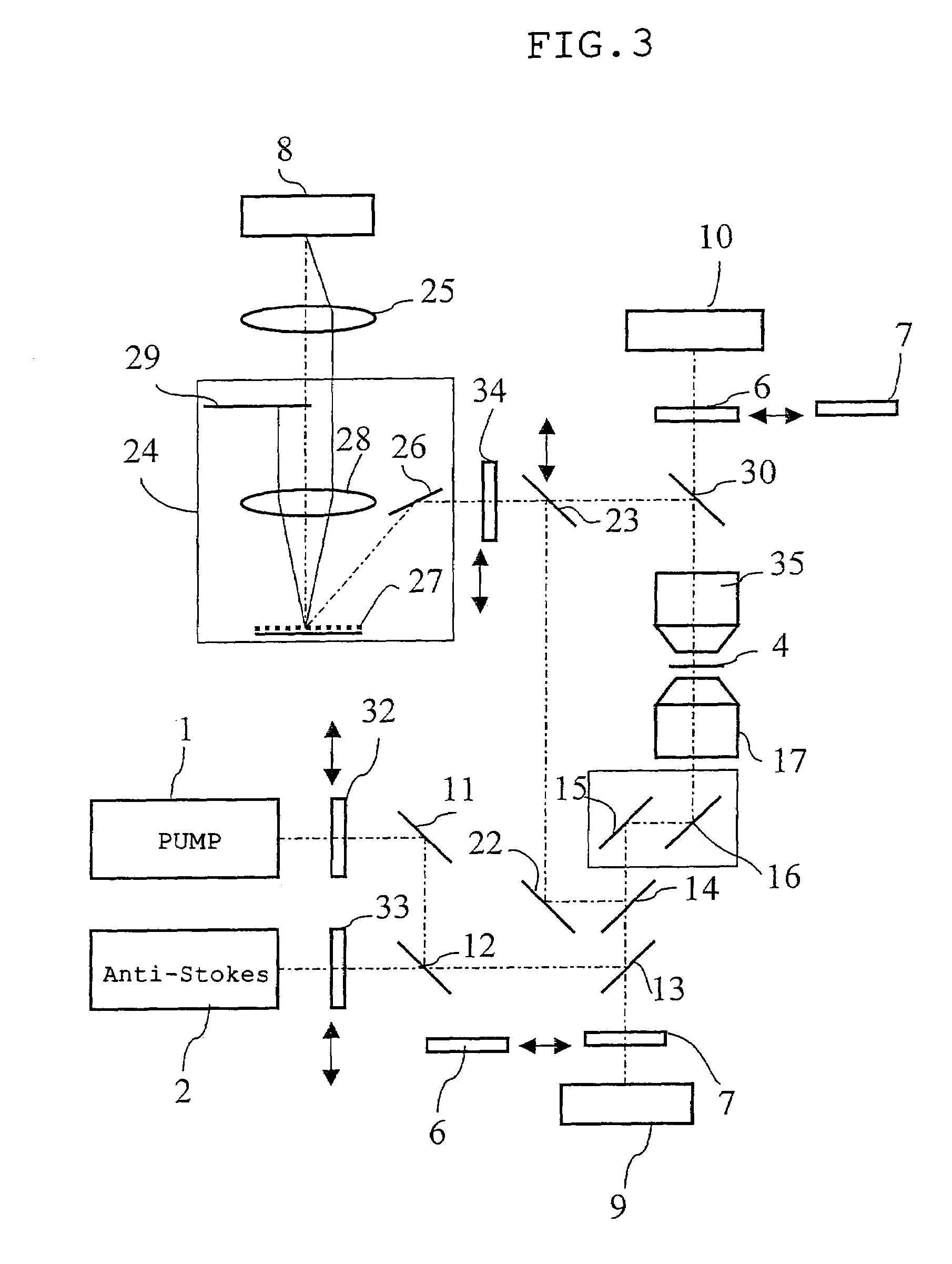
[0083]Hereafter, embodiments of the present invention will be explained using drawings. In diagrammatic charts of the drawings in the following embodiments, the following expressions are used: SHG denotes second harmonic wave, 2-P denotes multiphoton excitation fluorescence, Anti-Stokes denotes anti-Stokes light, Pump denotes pump light, CSRS denotes coherent Raman scattering light, Stokes denotes Stokes light, CARS denotes the coherent Raman scattering light, and 1-P denotes single photon excitation fluorescence. These symbols are commonly used in each of the following embodiments.
[0084]FIG. 3 is a diagram showing an optical composition of the microscope of the first embodiment according to the present invention. FIG. 4 is a diagrammatic chart showing optical characteristics of a dichroic mirror and a band pass filter used for the microscope in the first embodiment.
[0085]A microscope of the first embodiment comprises a first pulsed laser generating means 1 that generates a first pu...
second embodiment
[0124]FIG. 5 is a diagram showing an outlined composition of the microscope system of the second embodiment according to the present invention. FIG. 6 is a diagrammatic chart showing optical characteristics of a dichroic mirror and a band pass filter used for the microscope in the second embodiment.
[0125]In the microscope of the second embodiment, The half mirror 23 is fixed on the optical path where the light reflected by the mirror 22 and the light reflected by the dichroic mirror 30 are crossed, whereby its constitution is limited in such that the coherent Stokes Raman scattering light of both of the F-CSRS light and the E-CSRS light are extracted.
[0126]On an optical path at a penetration side of the dichroic mirror 14, a dichroic mirror 36a is arranged. In the dichroic mirror 13, light having a wavelength of the wavelength band (for example, about 350-450 nm) of the second harmonic wave of the second pulsed laser light transmits, and light having a wavelength longer than that of...
third embodiment
[0129]FIG. 7 is a diagram showing an outlined composition of the microscope system of the third embodiment according to the present invention. FIG. 8 is a diagrammatic chart showing optical characteristics of a dichroic mirror and a band pass filter used for the microscope in the third embodiment.
[0130]The microscope of the third embodiment comprises a first pulsed laser generating means 1′ that generates a first pulse light having a first wavelength component, a second pulsed laser generating means 2′ that generates a second pulse light having a second wavelength component, an irradiation means (symbol is omitted) which is constituted so that irradiation to the specimen 4 can be carried out by composing the first pulse light and the second pulse light, a coherent anti-Stokes Raman scattering light extraction means (symbol is omitted) which extracts only coherent anti-Stokes Raman scattering light from the light emanated from the specimen 4 to which irradiating light is irradiated t...
PUM
| Property | Measurement | Unit |
|---|---|---|
| pulse width | aaaaa | aaaaa |
| wavelength | aaaaa | aaaaa |
| wavelength band | aaaaa | aaaaa |
Abstract
Description
Claims
Application Information
 - R&D
- Intellectual Property
- Life Sciences
- Materials
- Tech Scout
- Unparalleled Data Quality
- Higher Quality Content
- 60% Fewer Hallucinations
Browse by: Latest US Patents, China's latest patents, Technical Efficacy Thesaurus, Application Domain, Technology Topic, Popular Technical Reports.
© 2025 PatSnap. All rights reserved.Legal|Privacy policy|Modern Slavery Act Transparency Statement|Sitemap|About US| Contact US: help@patsnap.com


