Deep quantum well electro-absorption modulator

a quantum well and modulator technology, applied in the field of deep quantum well electroabsorption modulator, can solve the problems of limited modulation speed, adverse modulation rate, higher capacitance, etc., and achieve the effect of increasing the quantum well absorption and increasing the extinction ratio of the electro-absorption modulator

Inactive Publication Date: 2008-10-28
AVAGO TECH WIRELESS IP SINGAPORE PTE
View PDF16 Cites 5 Cited by
  • Summary
  • Abstract
  • Description
  • Claims
  • Application Information

AI Technical Summary

Benefits of technology

[0005]In accordance with the invention, double well structures in electro-absorption modulators are created in quantum well active regions by embedding deep ultra thin quantum wells. The perturbation introduced by the embedded, deep ultra thin quantum well centered within a conventional quantum well lowers the confined energy state for the wavefunction in the surrounding larger well and typically results in the hole and electron distributions being more confined to the center of the conventional quantum well. The resulting increase in spatial overlap of the hole and electron wavefunctions increases the quantum well absorption. Hence, the extinction ratio provided by the electro-absorption modulator is typically increased.

Problems solved by technology

Because little current flows when the reverse bias is applied, the modulation speed is limited by the time required to charge and discharge the capacitance of the electro-absorption modulator.
There are a number of tradeoffs associated with multiple quantum well design of electro-absorption modulators and the impact on performance parameters.
Overall electro-absorption modulator design and operation typically represents a tradeoff among limitations.
However, the modulation rate is adversely effected because longer modulators result in higher capacitance and increasing the number of quantum wells increases carrier extraction time.

Method used


Image

  • Deep quantum well electro-absorption modulator
  • Deep quantum well electro-absorption modulator
  • Deep quantum well electro-absorption modulator

Examples


Embodiment Construction

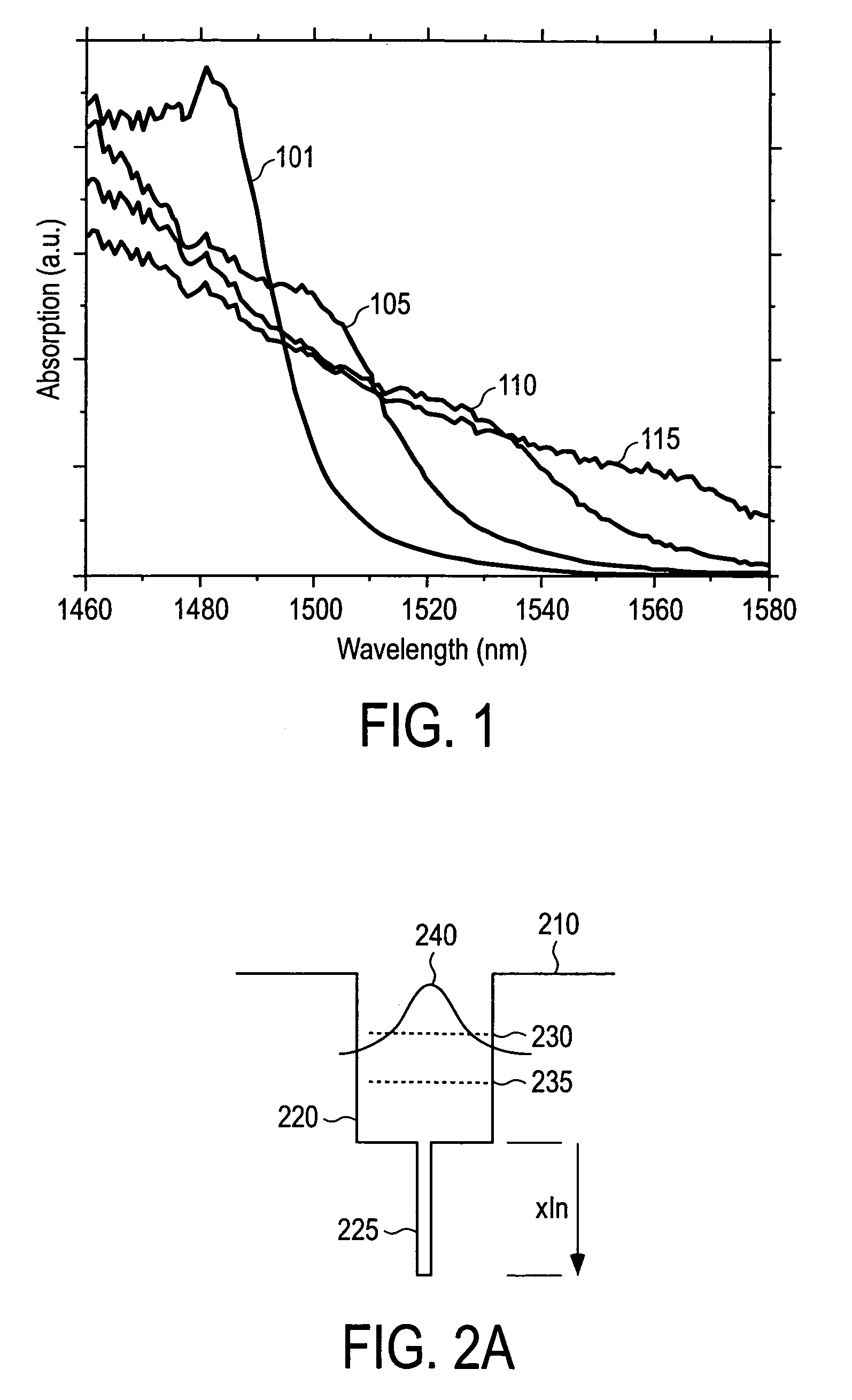
[0016]FIG. 2a shows a composition profile for a quantum well of an embodiment in accordance with the invention. GaAs barrier layer 210 provides the reference level of zero indium content at the top of InGaAs quantum well 220. InGaAs quantum well 220 is a highly strained quantum well in which embedded, deep, ultra-thin quantum well 225 is embedded into InGaAs quantum well 220 to make a subwell. Quantum well 220 is typical of quantum wells used on GaAs. The perturbation introduced by embedded, deep, ultra-thin quantum well 225 lowers confined energy state 230 of wavefunction 240 in quantum well 220 to confined energy state 235. A composition for embedded, deep, ultra-thin quantum well 225 is typically of the form InxGa(1-x)As given a typical composition for quantum well 220 of InyGa(1-y)As where y is typically in the range of about 0.35 to 0.4. The value of y is typically selected to achieve the longest wavelength possible from quantum well 220 without the addition of embedded, deep u...


PUM

PropertyMeasurementUnit
thicknessaaaaaaaaaa
thicknessaaaaaaaaaa
thicknessaaaaaaaaaa

Abstract

Double well structures in electro-absorption modulators are created in quantum well active regions by embedding deep ultra thin quantum wells. The perturbation introduced by the embedded, deep ultra thin quantum well centered within a conventional quantum well lowers the confined energy state for the wavefunction in the surrounding larger well and typically results in the hole and electron distributions being more confined to the center of the conventional quantum well. The extinction ratio provided by the electro-absorption modulator is typically increased.

Description

BACKGROUND[0001]Electro-absorption modulators are used to modulate light in optical telecommunications applications. Typically, an electro-absorption modulator modulates light generated by a continuous light source. The electro-absorption modulator typically modulates light by either allowing or preventing light from passing through the electro-absorption modulator. One of the main parameters that characterize the light modulation performance of an electro-absorption modulator is the extinction ratio. The extinction ratio is the ratio of the maximum power output to the minimum power output of the electro-absorption modulator. A higher extinction ratio is typically the result of a higher absorption of light through the creation of more electron-hole pairs in the active layer.[0002]Electro-absorption modulators capable of operating at data rates on the order of 40 Gb / s are of interest for optical telecommunications applications. Electro-absorption modulators are typically based on the...

Claims


Application Information

Patent Timeline
Patent Type & Authority Patents(United States)
IPC IPC(8): G02F1/03H01L29/06H01S5/00
CPCB82Y20/00G02F1/017G02F1/01725G02F2001/01766G02F2202/101G02F2202/102G02F1/01766H01S3/10H01S5/00
Inventor BOUR, DAVID P.TANDON, ASHISHTAN, MICHAEL R. T.
Owner AVAGO TECH WIRELESS IP SINGAPORE PTE
Why Eureka
Try Eureka