Exhaust gas control apparatus for internal combustion engine

a control apparatus and gas control technology, applied in mechanical devices, electric control, machines/engines, etc., can solve the problem of not giving enough consideration to which portion, and achieve the effect of suppressing unnecessary decrease in combustion temperature, high temperature of egr gas supplied to the internal combustion engine, and promoting evaporation (atomization) of fuel

Inactive Publication Date: 2008-11-04
TOYOTA JIDOSHA KK
View PDF22 Cites 22 Cited by
  • Summary
  • Abstract
  • Description
  • Claims
  • Application Information

AI Technical Summary

Benefits of technology

[0013]Meanwhile, when the EGR gas is taken out from the portion upstream of the particulate filter while the PM trapping ability forcible recovery process is being performed, the amount of the exhaust gas flowing into the particulate filter is decreased. Therefore, the temperature of the particulate filter may be excessively increased. Therefore, it is conceivable to prohibit the exhaust gas from being recirculated while the PM trapping ability forcible recovery control is being performed. However, if the exhaust gas is prohibited from being recirculated while the PM trapping ability forcible recovery process is being performed, an amount of generated NOx may be increased.
[0029]In the aforementioned exhaust gas control apparatus for an internal combustion engine, when the PM trapping ability forcible recovery process of the particulate filter is performed, it is possible to perform the EGR control while suppressing an excessive increase in the temperature of the particulate filter and a decrease in stability of combustion.

Problems solved by technology

Meanwhile, in the aforementioned related art, sufficient consideration is not given to which portion should be supplied with the EGR gas that is taken out from the portion downstream of the particulate filter.

Method used


Image

  • Exhaust gas control apparatus for internal combustion engine
  • Exhaust gas control apparatus for internal combustion engine
  • Exhaust gas control apparatus for internal combustion engine

Examples


Embodiment Construction

[0034]In the following description and the accompanying drawings, the present invention will be described in more detail in terms of exemplary embodiments.

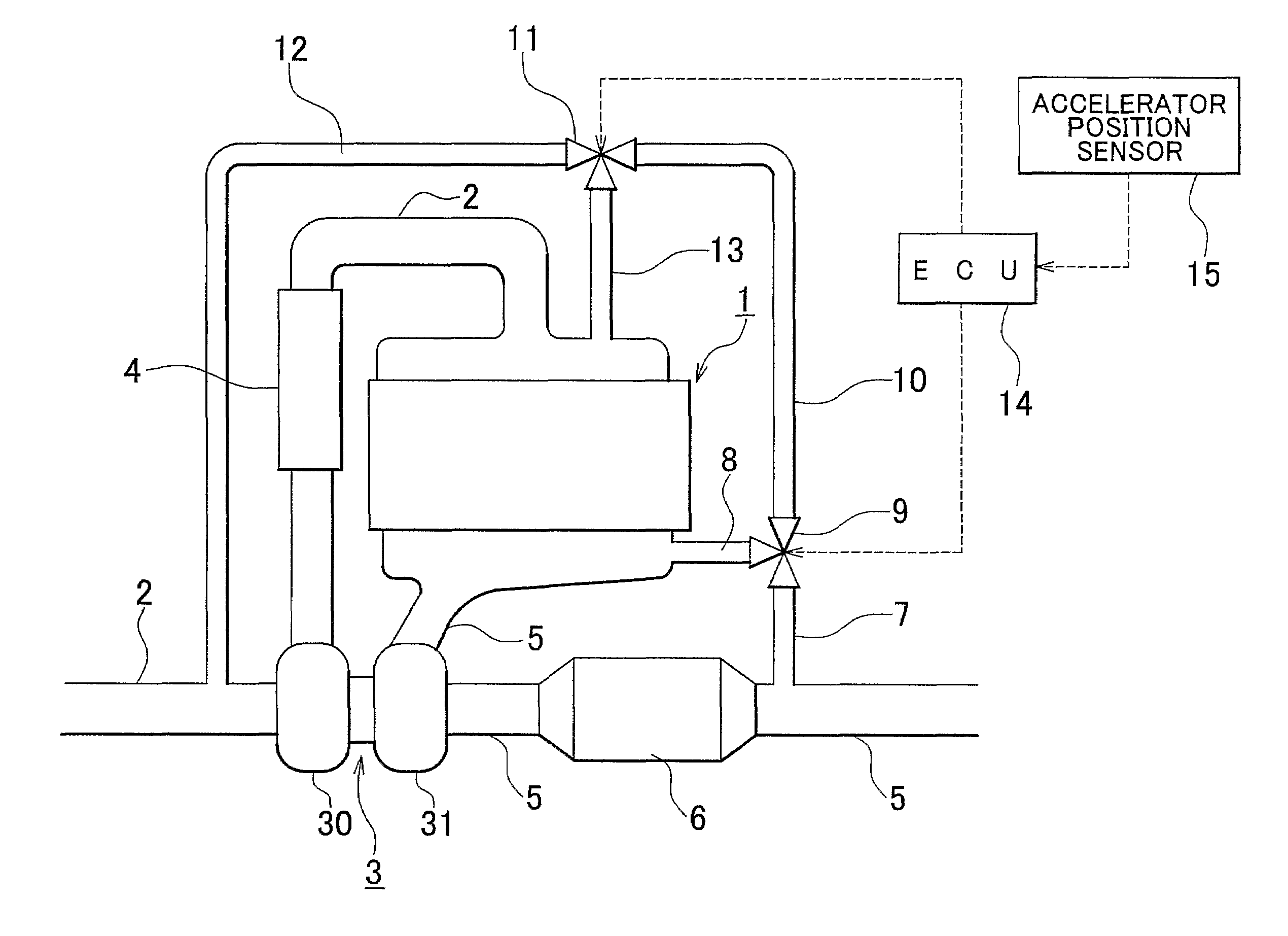
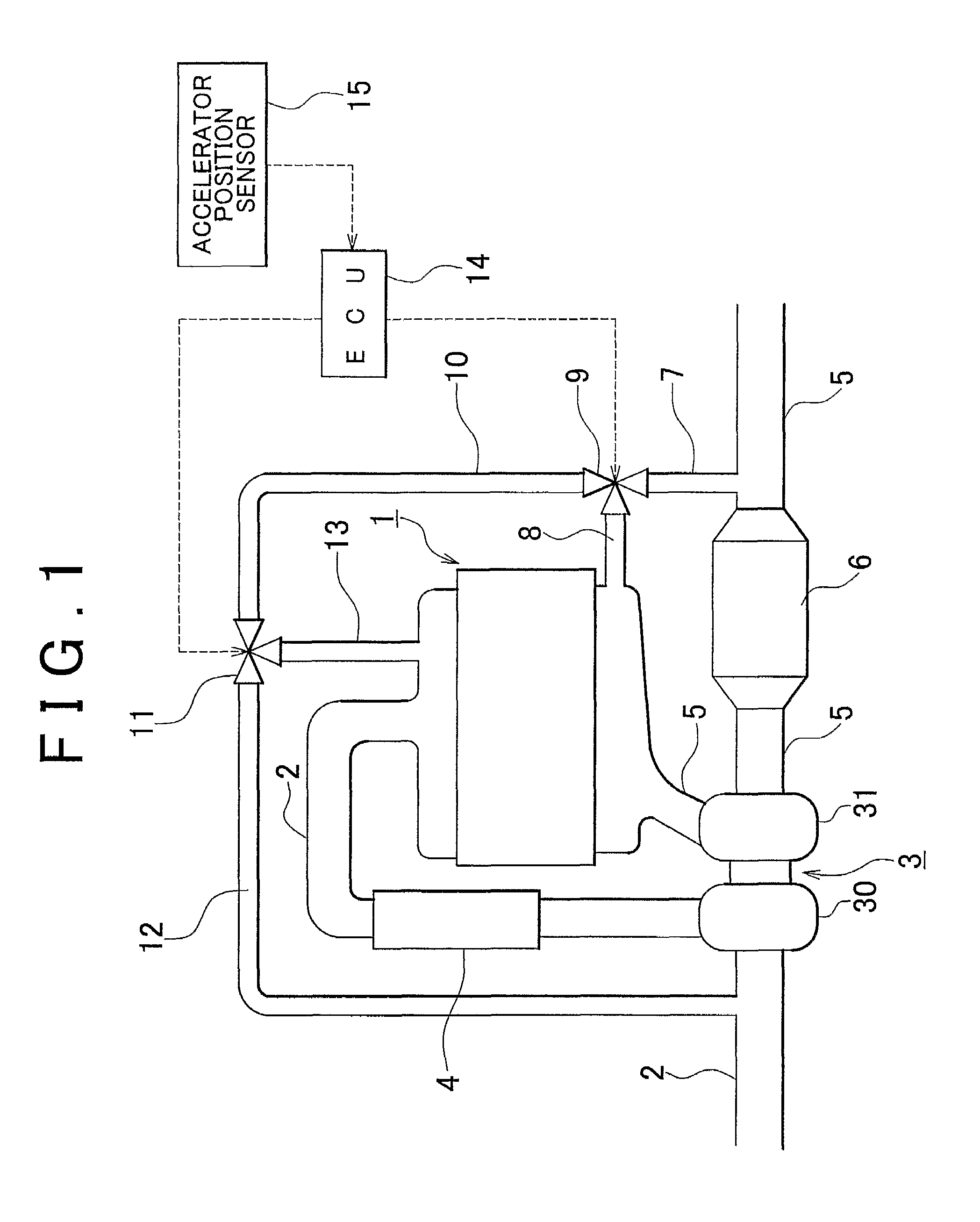
[0035]Hereinafter, an exhaust gas control apparatus according to an exemplary embodiment of the invention will be described with reference to the accompanying drawings. FIG. 1 is a schematic diagram showing a configuration of an internal combustion engine to which an embodiment of the invention is applied. An internal combustion engine 1 shown in FIG. 1 is a compression ignition internal combustion engine (diesel engine).

[0036]An intake passage 2 is connected to the internal combustion engine 1. In the intake passage 2, a compressor housing 30 of a centrifugal supercharger (in this embodiment, a turbocharger) 3 is provided. An intercooler 4 is provided at a portion downstream of the compressor housing 30 in the intake passage 2.

[0037]Also, an exhaust passage 5 is connected to the internal combustion engine 1. A turbine housing 31 ...


PUM


Abstract

In an exhaust gas control apparatus for an internal combustion engine, in a case where an internal combustion engine is in a high load operating state while a PM trapping ability forcible recovery process for a particulate filter is being performed, EGR gas is caused to flow back from a portion downstream of the particulate filter in an exhaust passage to a portion upstream of a compressor housing in an intake passage, whereby the EGR gas is cooled by an intercooler. In a case where the internal combustion engine is in a low load operating state while the PM trapping ability forcible recovery process is being performed, the EGR gas is caused to flow back from the portion downstream of the particulate filter in the exhaust passage to a portion downstream of the intercooler in the intake passage, whereby the EGR gas is prevented from being unnecessarily cooled.

Description

[0001]The disclosure of Japanese Patent Application No. 2004-203185 filed on Jul. 9, 2004, including the specification, drawings and abstract is incorporated herein by reference in its entirety.BACKGROUND OF THE INVENTION[0002]1. Field of the Invention[0003]The invention relates to an exhaust gas control apparatus for an internal combustion engine. More particularly, the invention relates to an exhaust gas control apparatus including a particulate filter and an EGR mechanism.[0004]2. Description of the Related Art[0005]Recently, an exhaust gas control apparatus for an internal combustion engine including a particulate filter and an EGR mechanism has been widely used. Japanese Patent Application Publication No. JP (A) 4-22705 discloses an example of such an exhaust gas control apparatus, in which EGR gas is taken out from a portion downstream of a particulate filter. Also, Japanese Utility Model Application Publication No. 6-34122 and Japanese Patent No. 2675405 disclose related art....

Claims


Application Information

Patent Timeline
Patent Type & Authority Patents(United States)
IPC IPC(8): F01N3/00
CPCF01N3/023F02D41/0007F02D41/0055F02D41/029F02M25/0718F02M25/0728F02B37/00F02D41/0065F02D41/0245F02D2041/0017F02M25/0709F02M25/0796Y02T10/144Y02T10/47F02M26/06F02M26/15F02M26/25F02M26/71Y02T10/12Y02T10/40
Inventor HASHIZUME, TAKESHI
Owner TOYOTA JIDOSHA KK
Why Eureka
Try Eureka