Device for measuring in three dimensions a topographical shape of an object

a topographical shape and three-dimensional technology, applied in the field of three-dimensional topographical shapes of objects, can solve the problems of not being the most appropriate choice, requiring some power, and being relatively heavy set-up, and achieve the effect of fast measurement and high speed

Inactive Publication Date: 2008-11-04
ICOS VISION SYST
View PDF9 Cites 33 Cited by
  • Summary
  • Abstract
  • Description
  • Claims
  • Application Information

AI Technical Summary

Benefits of technology

[0005]It is an object of the present invention to realise a device and/or a method for measuring, in three dimensions, a shap

Problems solved by technology

A drawback of the known device and method is that the confocal topographical mask as well as the light path diverging optical element, the sensor members and the confocal objective are all moved together in the z-direction in ord

Method used


Image

  • Device for measuring in three dimensions a topographical shape of an object
  • Device for measuring in three dimensions a topographical shape of an object
  • Device for measuring in three dimensions a topographical shape of an object

Examples


Embodiment Construction

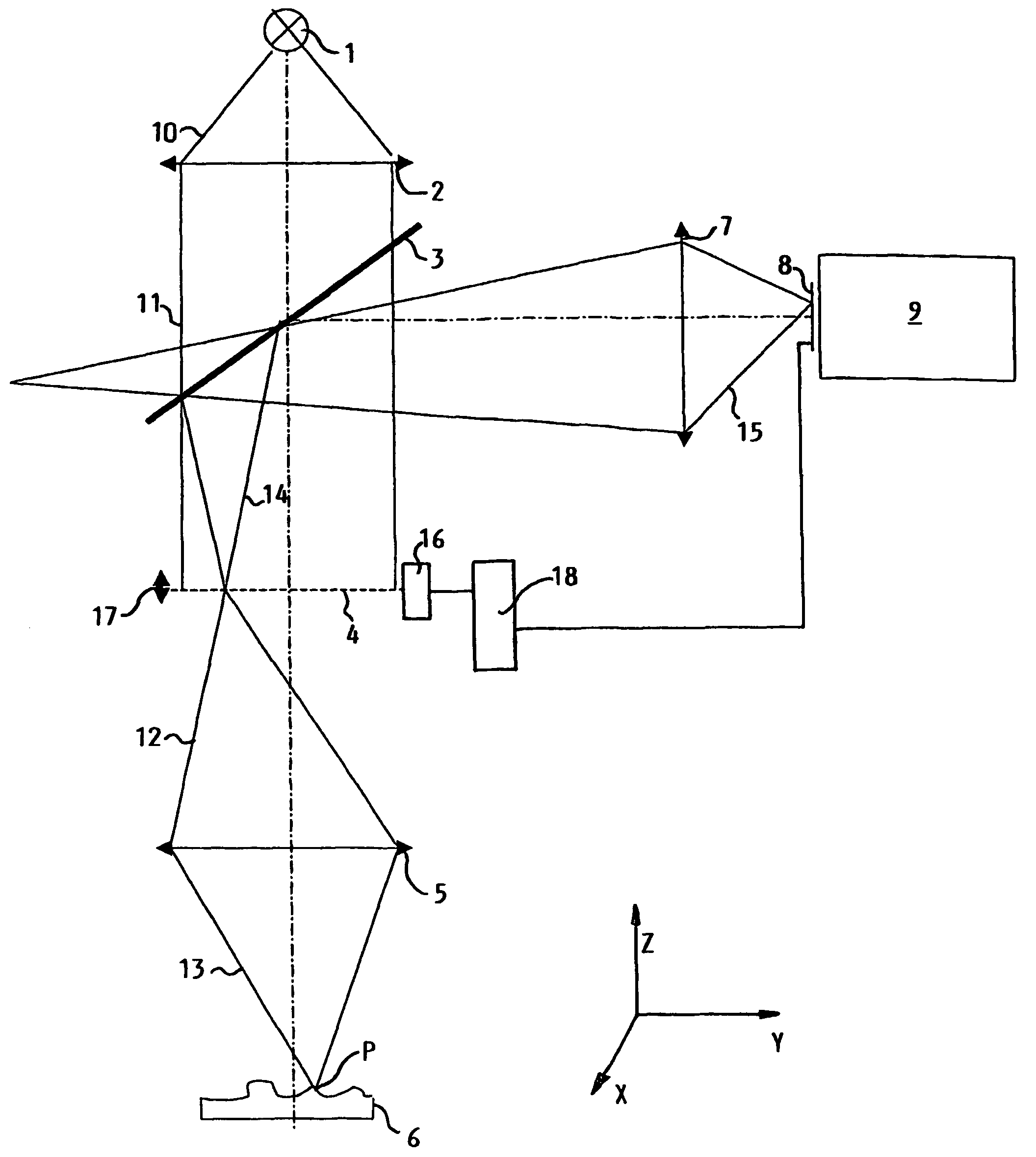
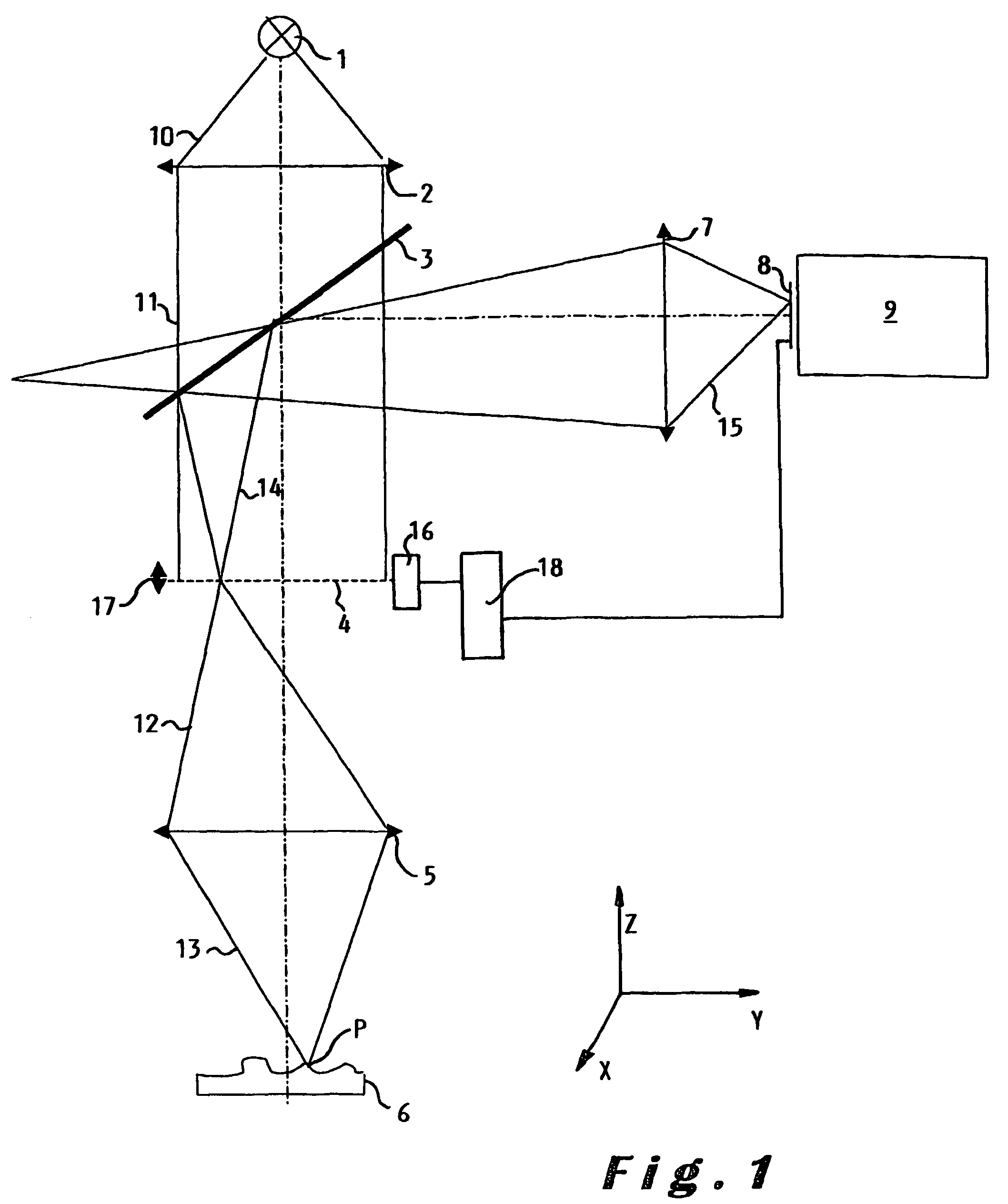
[0027]The present invention relates to a device and also a method for measuring, in three dimensions, a topographical shape of an object, i.e. 3D surface profiles, with a speed compatible to the one used in industrial manufacturing processes. For on-line applications within a manufacturing process, the time allotted for such a measurement is about 0.1 sec and preferably less. The objects to be measured generally have dimensions xyz=50×50×3 mm, wherein z indicates the height direction. The required accuracy is in the few micron range, in particular when electronic components are considered. It will however be clear that the present invention is not limited to the examples given here before. Nevertheless and for the sake of clarity, the referred example will be used throughout the description.

[0028]The device according to the invention comprises an arrayed confocal imaging system. The basic principle of a confocal imaging system is described in “confocal scanning optical microscopy an...


PUM


Abstract

A device for measuring in three dimensions a topographical shape of an object. The device comprises an arrayed confocal imaging system having a confocal topographical mask provided for converting light produced by a light source into an array of small spots. The mask being mounted on a scanning member provided for moving the mask over successive positions over a predetermined distance. The device further comprises a confocal objective provided for mapping at successive object-position-in-focus the array of small spots output at said successive positions. The confocal objective may be mounted at a fixed position within said device.

Description

BACKGROUND OF THE INVENTION[0001]The present invention relates to a device for measuring in three dimensions a topographical shape of an object, said device comprising an arrayed confocal imaging system having a light source provided for illuminating said object and a light path diverging optical element, provided for diverging a path of illuminating light output by said light source and a path of reflected light reflected by said object, said confocal imaging system further comprises a confocal topographical mask provided for converting illuminating light coming out from said light path diverging optical element into an array of small spots, said confocal imaging system further comprises a confocal objective provided for orienting said illuminating light towards said object and said reflected light towards said confocal topographical mask in order to form a confocal image, said device further comprises a photoelectric sensor member provided to receive said reflected light having pa...

Claims


Application Information

Patent Timeline
IPC IPC(8): G01B11/24G01B9/04G01B11/02G06T1/00
CPCG01B9/04G01B11/026G01B11/24G02B21/0024G02B21/0052G02B21/008
Inventor ZABOLITZKY, JOHNSMETS, CARLVERLUYTEN, LUDOSMEYERS, AUGUST
Owner ICOS VISION SYST
Why Eureka
Try Eureka