
Heat pipe cooled superconducting magnets with ceramic coil forms

a superconducting magnet and ceramic coil technology, applied in the field of magnetic resonance imaging (mri), can solve the problems of adversely affecting image quality, structural or thermal problems, eddy current generation, unwanted field distortion in imaging volume, etc., and achieve small and negligible eddy currents, reduce the formation of eddy currents, and reduce the effect of eddy current formation

Active Publication Date: 2008-11-11
GENERAL ELECTRIC CO
View PDF6 Cites 25 Cited by
  • Summary
  • Abstract
  • Description
  • Claims
  • Application Information

AI Technical Summary

Benefits of technology

[0007]The present invention overcomes the aforementioned drawbacks by providing a superconducting magnet assembly for use in an MRI system, and a method of manufacturing thereof, that reduces the formation of eddy currents. More specifically, the present invention is directed to provide a magnet assembly having a thermal and cooling system that produces very small and negligible eddy currents when exposed to an AC field.

Problems solved by technology

When formed of such metals, the cryostat and helium vessel are strong enough to resist vacuum forces; however, they generate eddy currents and unwanted field distortions in the imaging volume when exposed to an AC field, such as an AC field generated by gradient coils of the MR system.
The eddy currents in the cryostat and helium vessel of a MRI system generate un-wanted field distortions in the imaging volume and adversely affect the image quality.
The eddy current heating may also cause structural or thermal problems.
That is, the AC losses add to the total heat load and increase costs for maintaining the helium at a cryogenic temperature.
Better shielded gradient coils can reduce magnetic coupling; however, such a shielded gradient system is inefficient and requires high current and power.
Other compensation techniques can also be used to reduce the impact of the induced current and B0 field changes, but cannot completely eliminate the problem.

Method used


Image

  • Heat pipe cooled superconducting magnets with ceramic coil forms
  • Heat pipe cooled superconducting magnets with ceramic coil forms
  • Heat pipe cooled superconducting magnets with ceramic coil forms

Examples


Embodiment Construction

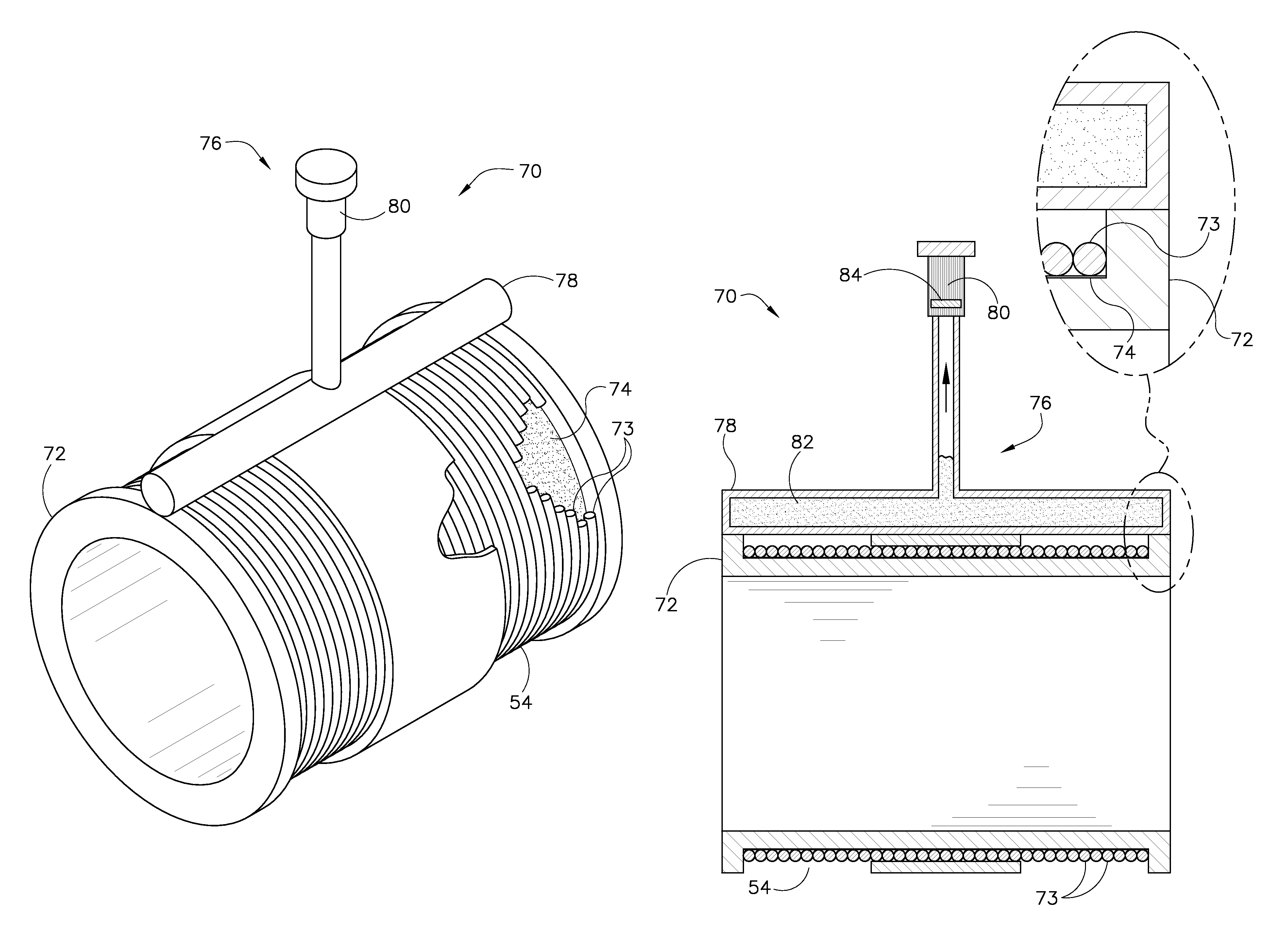
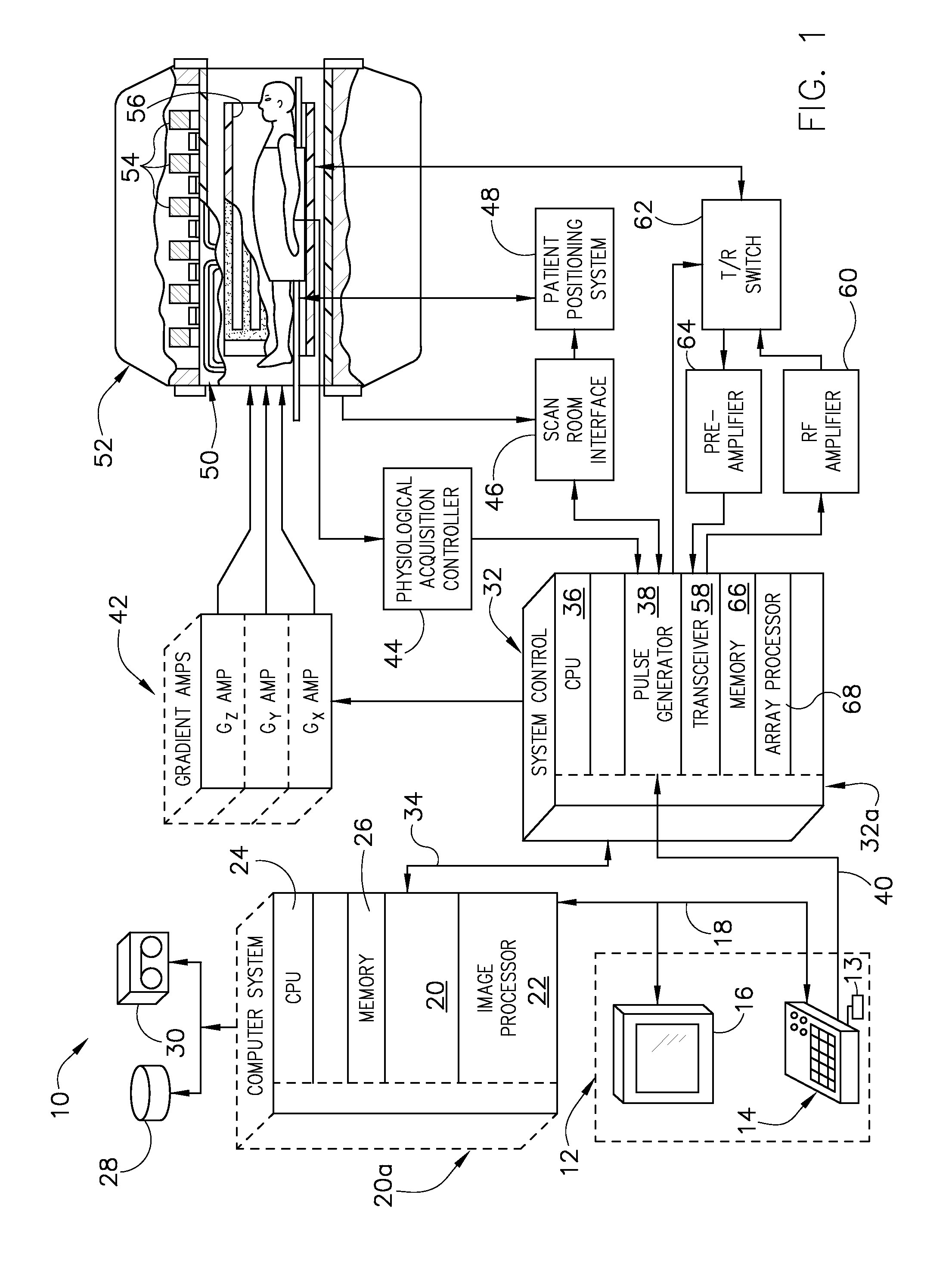
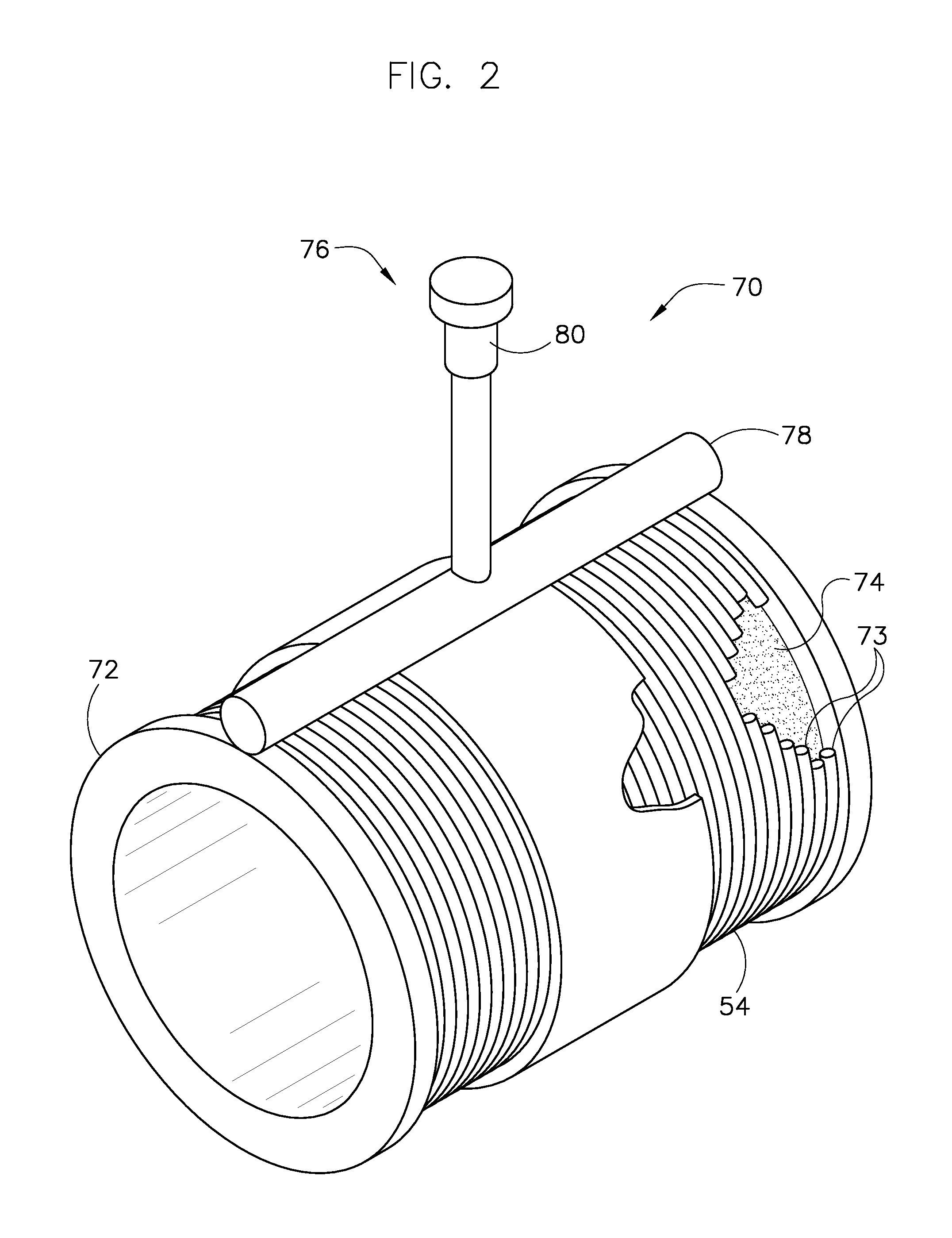
[0017]Referring to FIG. 1, the major components of a preferred magnetic resonance imaging (MRI) system 10 incorporating the present invention are shown. The operation of the system is controlled from an operator console 12 which includes a keyboard or other input device 13, a control panel 14, and a display screen 16. The console 12 communicates through a link 18 with a separate computer system 20 that enables an operator to control the production and display of images on the display screen 16. The computer system 20 includes a number of modules which communicate with each other through a backplane 20a. These include an image processor module 22, a CPU module 24 and a memory module 26, known in the art as a frame buffer for storing image data arrays. The computer system 20 is linked to disk storage 28 and tape drive 30 for storage of image data and programs, and communicates with a separate system control 32 through a high speed serial link 34. The input device 13 can include a mous...


PUM


Abstract

A system and method for a magnetic resonance (MR) imaging system includes a coil form, at least one magnet positioned about the coil form and configured to generate a magnetic field, at least one gradient coil for manipulating the magnetic field generated by the at least one magnet by way of a gradient field, and a heat pipe thermally connected to the coil form and having a cryogen therein. The MR imaging system also includes a cryocooler connected to the heat pipe to cool the heat pipe and the cryogen, wherein the coil form is comprised of a thermally conductive material in which eddy currents are substantially reduced during operation of the at least one gradient coil. The present invention has been described in terms of the preferred embodiment, and it is recognized that equivalents, alternatives, and modifications, aside from those expressly stated, are possible and within the scope of the appending claims.

Description

BACKGROUND OF THE INVENTION[0001]The present invention relates generally to a magnetic resonance imaging (MRI) system and more particularly to a superconducting magnet assembly in the MRI system and a process for manufacturing the superconducting magnet assembly.[0002]MRI systems utilize superconducting magnets to generate a strong, uniform magnetic field within which a patient or other subject is placed. Magnetic gradient coils and radio-frequency transmit and receive coils then influence gyromagnetic materials in the subject to provoke signals that can be used to form useful images. Other systems that use such coils include spectroscopy systems, magnetic energy storage systems, and superconducting generators.[0003]In use with MRI, a superconducting magnet is disposed in a cryostat that includes a thermal shield and a vacuum vessel that insulate the magnet from the environment during operation. The superconducting magnet also has a coil support structure to support the coil in a co...

Claims


Application Information

Patent Timeline
IPC IPC(8): G01V3/00
CPCG01R33/3802G01R33/3804G01R33/3815
Inventor HUANG, XIANRUIAKSEL, BULENTAMM, KATHLEEN M.LASKARIS, EVANGELOS T.STAUTNER, ERNST W.THOMPSON, PAUL S.WU, ANBOXU, MINFENGZHAO, YAN
Owner GENERAL ELECTRIC CO
Learn More