Grinding method

a grinding method and honeycomb technology, applied in the direction of grinding machine components, other manufacturing equipment/tools, manufacturing tools, etc., can solve the problems of reducing yield, affecting the operation of grinding wheels, and affecting the proportion of the finished product, so as to improve the operability of the grinding wheel, reduce the processing time, and improve the processability

Active Publication Date: 2008-11-18
NGK INSULATORS LTD
View PDF9 Cites 14 Cited by
  • Summary
  • Abstract
  • Description
  • Claims
  • Application Information

AI Technical Summary

Benefits of technology

[0018]The method shown in FIG. 12 reduces the amount of cutting “J” of the grinding wheel 12. Specifically, grinding is controlled so that the amount of the honeycomb structure 5 ground by the grinding wheel 12 is reduced. The size of the chip 13 removed from the honeycomb structure 5 is reduced by reducing the amount of cutting “J”, whereby the breakage 14 occurring on the other end 5b of the honeycomb structure 5 can be reduced. However, the method shown in FIG. 12 has a problem in which the number of cutting operations until the honeycomb structure 5 has a desired outer diameter is increased, whereby the processing time is increased.
[0035]According to the first grinding method and the second grinding method of the present invention, the lifetime of the grinding wheel is increased, whereby productivity can be further improved.

Problems solved by technology

Moreover, since the same portion of the grinding wheel 12 contacts the honeycomb structure 5 during cutting, this portion is worn away to a large extent, whereby the processed surface of the honeycomb structure 5 may be impaired.
Since such chipping results in a defective product, the yield is decreased.

Method used


Image

  • Grinding method
  • Grinding method
  • Grinding method

Examples


first embodiment

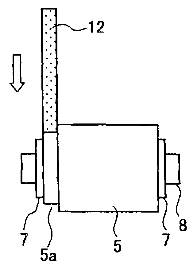
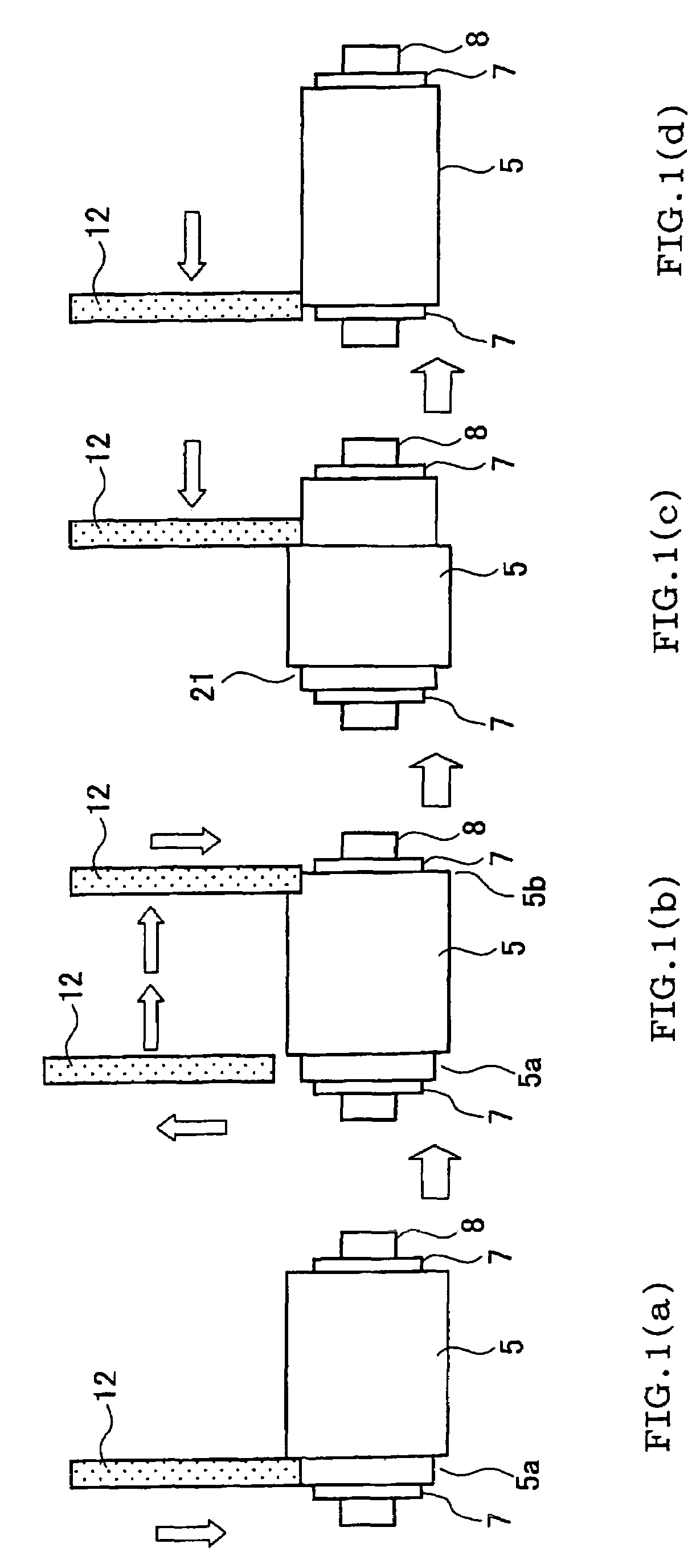
[0058]FIG. 1 is a view showing a grinding process according to the grinding method of the present invention. The ends of the honeycomb structure 5 (workpiece) in the longitudinal direction are held using the pressing plates 7 formed of an elastic material such as rubber. The pressing plate 7 is attached to the rotational axis (rotary shaft) 8 connected with a motor (not shown). The honeycomb structure 5 is rotated during grinding due to rotation of the rotational axis 8.

[0059]As the grinding wheel 12, a flat grinding wheel having a width smaller than the length of the honeycomb structure 5 is used. The grinding wheel 12 is caused to come in contact with the honeycomb structure 5 while being rotated to grind the honeycomb structure 5.

[0060]In the first embodiment shown in FIG. 1, plunge grinding and traverse grinding are performed in combination, with the traverse grinding being performed after the plunge grinding.

[0061]In plunge grinding, as shown in FIG. 1(a), the grinding wheel 12...
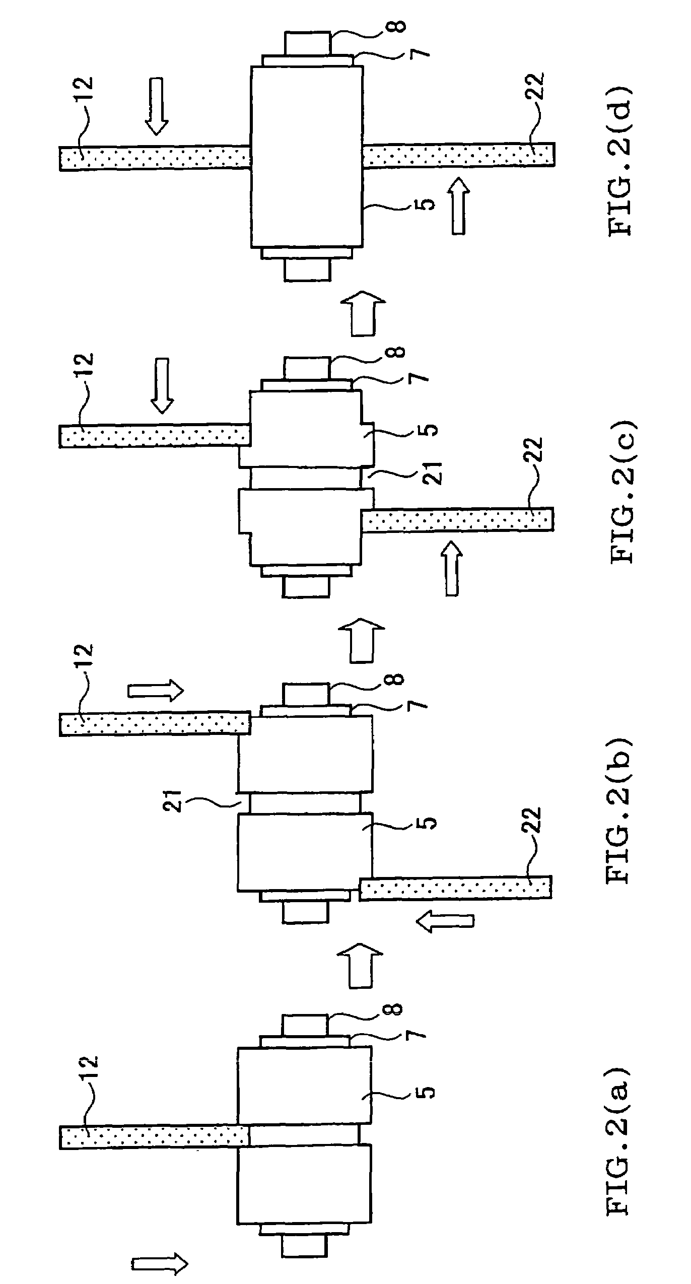
third embodiment

[0072] since the process is completed by the first-stage and second-stage traverse grinding without requiring plunge grinding, the processing time can be reduced. Moreover, since chipping does not occur in the final stage of the second-stage traverse grinding, a complicated chipping prevention operation is made unnecessary, whereby the processability can be improved.

[0073]Table 1 shows qualitative comparison among the above-described embodiments and known grinding methods. A method “A” corresponds to the method according to the first embodiment, a method “B” corresponds to the method according to the second embodiment, and a method “C” corresponds to the method according to the third embodiment. The value shown in Table 1 indicates the ratio with respect to known plunge grinding (“1”). The methods “A” to “C” have advantages over the known grinding methods.

[0074]

TABLE 1Known traverse grindingWhen theamount ofWhen dummyKnown plungeNormal traversecutting wasmaterial wasEmbodimentgrindi...


PUM

PropertyMeasurementUnit
rotational speedaaaaaaaaaa
brittleaaaaaaaaaa

Abstract

A method of grinding the outer circumferential surface of a workpiece 5 formed of a hard and brittle material into a predetermined shape using a grinding wheel while rotating the workpiece 5 is disclosed. The method includes plunge grinding the workpiece 5 at an arbitrary portion (plunge ground portion 21) in the longitudinal direction of the workpiece 5 by causing the grinding wheel to come in contact with the workpiece 5 in a direction which intersects a rotational axis 8 of the workpiece 5, and traverse grinding the workpiece 5 toward the plunge ground portion 21 by moving the grinding wheel relative to the workpiece 5 in a direction parallel to the rotational axis 8 of the workpiece 5. This allows the outer circumferential surface of the workpiece made of a hard and brittle material, such as a honeycomb structure used for a DPF, to be ground into a predetermined shape in a short time, and prevents occurrence of chipping during grinding.

Description

TECHNICAL FIELD[0001]The present invention relates to a method of grinding the outer circumferential surface of a workpiece formed of a hard and brittle material.BACKGROUND ART[0002]A diesel particulate filter (DPF) is provided for a diesel internal combustion engine in order to trap diesel particulate contained in exhaust gas discharged from the engine. A DPF is formed by bonding porous honeycomb segments formed of silicon carbide (SiC) or the like using an adhesive. The outer circumferential surface of the segment bonded body obtained by bonding the honeycomb segments is ground to form a honeycomb structure having an arbitrary shape (e.g. circle or ellipse), and the outer circumferential surface is coated with a coating material.[0003]FIGS. 4 to 6 are views showing the manufacturing steps of a honeycomb structure used for a DPF. As shown in FIG. 4, an original form 1 of a honeycomb structure has a large quadrilateral cross section formed by bonding honeycomb segments 2 having a qu...

Claims


Application Information

Patent Timeline
Patent Type & Authority Patents(United States)
IPC IPC(8): B24B49/00B24B1/00B24B5/04
CPCB24B1/00B24B5/04
Inventor ITOH, YUJINORO, TAKASHI
Owner NGK INSULATORS LTD
Why Eureka
Try Eureka