
Automated creation of metrology recipes

a technology of automated creation and metrology, applied in the field of metrology, can solve the problems of limiting the number of measurement locations that can be practically set up, requiring skilled engineers, and consuming the manual process of finding locations and taking images, so as to improve the accuracy and throughput of the manufacturing process

Active Publication Date: 2008-11-25
SYNOPSYS INC
View PDF25 Cites 20 Cited by
  • Summary
  • Abstract
  • Description
  • Claims
  • Application Information

AI Technical Summary

Benefits of technology

[0011]For a manufacturing process, such as integrated circuit manufacturing and lithographic mask manufacturing, in which patterns to be formed are defined using a design database, features for metrology are determined by processing the design database, including in some embodiments, reviewing simulated images of features in the design. Images used for alignment of the measurement tool are simulated, locations for measurement on the selected features are set, and other tool specific recipe data is provided for the selected locations. A graphical user interface facilitates the selection of features, the setting of measurement locations on the features, and the capturing of simulated images of the features. The present invention is used with a variety of metrology tools including, but not limited to, the following:
[0023]In yet another embodiments, a graphical user interface is utilized in which simulated images of the device are presented to a user, and input tools are used for selecting the features for measurements. Simulated images can also identify where there are process sensitive locations in the layout, likely to cause a problem for the device on the wafer. Error flags, such as those provided in commercially available SiVL® software from Numerical Technologies, Inc, of San Jose, Calif., can be used to identify such locations. The selected features are then presented in a manner that facilitates identifying a location on the selected feature for measurement, and for capturing a simulated image of the feature for use in aligning the metrology tool at the identified location on the feature in a real device.
[0027]In yet another embodiments, the design database comprises a hierarchical database, with nodes in hierarchy corresponding with features on the device. The recipe data in this embodiment is linked with corresponding nodes in hierarchy, enabling reuse and improving efficiency of the metrology set up process.
[0029]Other embodiments of the invention comprise manufacturing lines, in which metrology is utilized in real-time control for manufacturing, based on recipe data provided as described above, improving the accuracy and throughput of the manufacturing process.

Problems solved by technology

However, in prior art approaches, the set of features to be measured is manually selected, and the metrology tools are manually set up by skilled engineers, using painstaking study of the layout.
Therefore, the set of features to be measured must be efficiently determined and limited to a number that can be effectively achieved without undue expense.
The manual process of finding locations and taking the images can be very time-consuming, requires skilled engineers, and limits the number of measurement locations that can be practically set up.
The problem of selecting which features to inspect on a device, further complicates the metrology set up process, for devices having millions of features defined by lithography.

Method used


Image

  • Automated creation of metrology recipes
  • Automated creation of metrology recipes
  • Automated creation of metrology recipes

Examples


Embodiment Construction

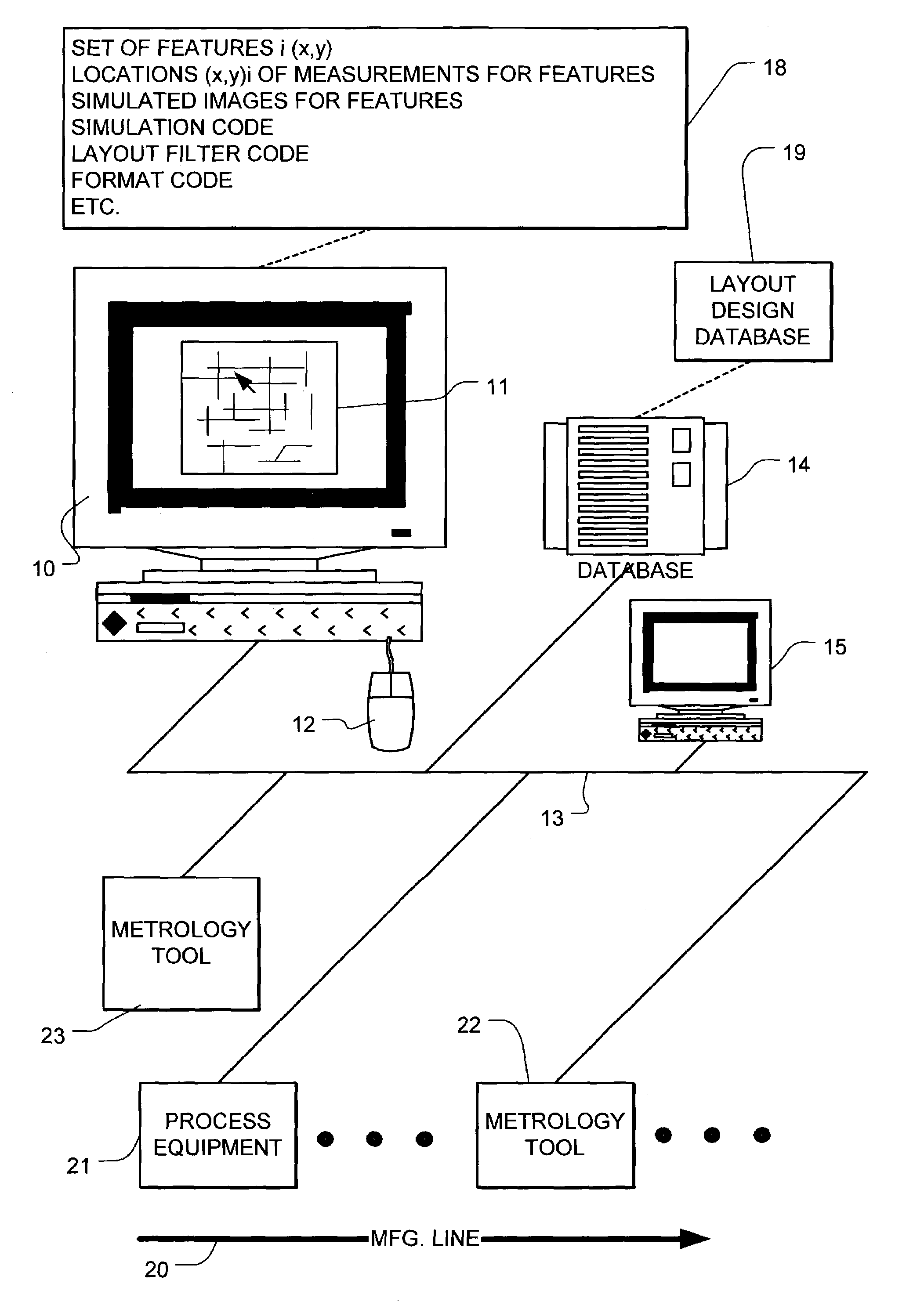
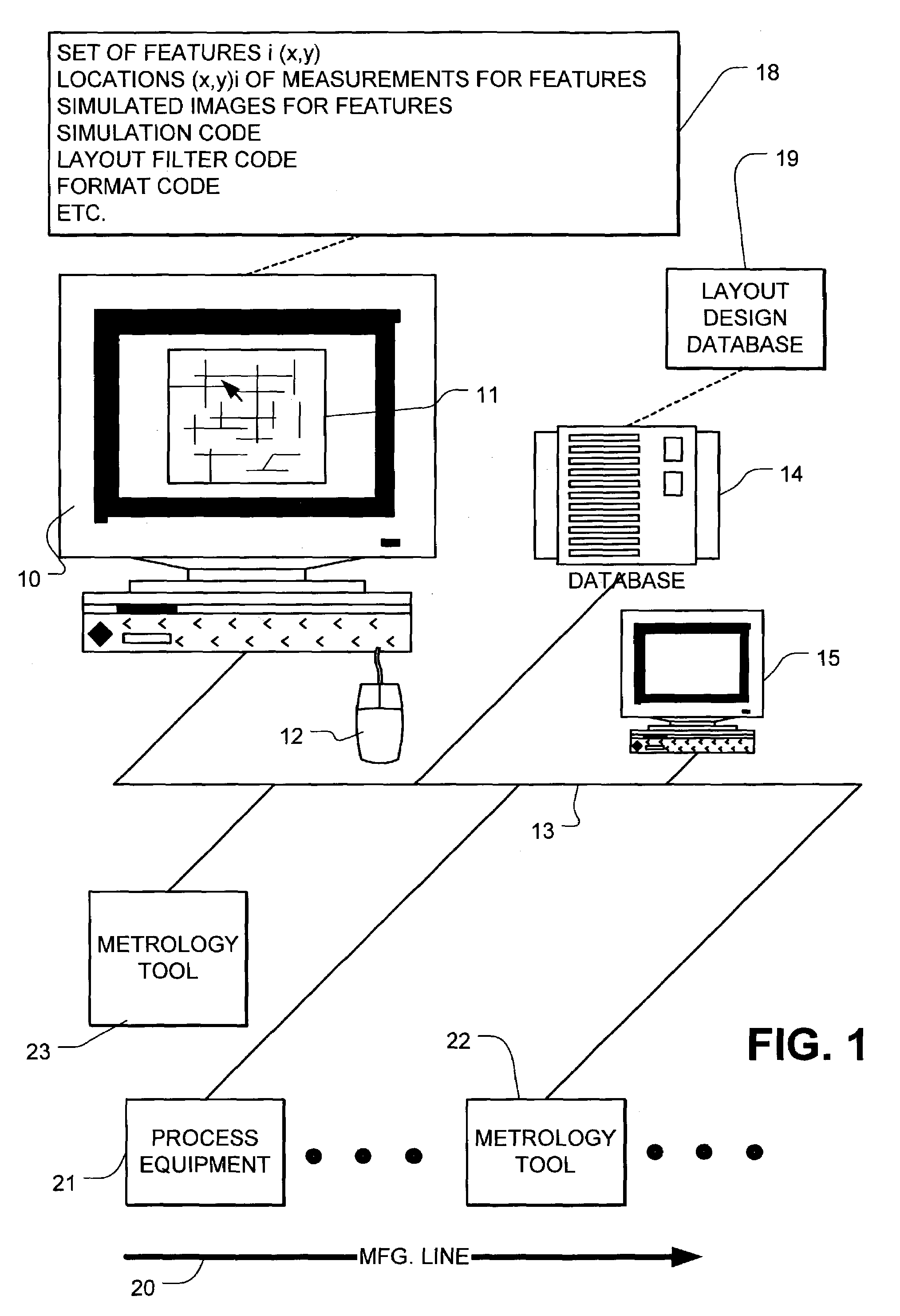
[0040]A detailed description of embodiments of the present invention is provided with reference to FIGS. 1-9. FIG. 1 schematically illustrates a manufacturing line 20 including process equipment 21 coupled with a metrology system, including metrology tool 22, metrology tool 23, and a data processing system, including workstations 10 and 15 and database storage system 14, executing programs of instruction, implemented with features of the present invention. The metrology tools 22, 23 include controllers coupled to the network 13, which execute programs of instruction in support of the measurement process. In a preferred system, the manufacturing line 20 comprises an integrated circuit fabrication line, applying lithographic techniques for the definition of features in layers of material used for implementation of integrated circuits on semiconductor wafers. In other embodiments, the manufacturing line comprises a lithographic mask manufacturing line.

[0041]Components of the system sho...


PUM


Abstract

An automated metrology recipe set up process is described for a manufacturing process, in which patterns to be formed on a device are defined using a design database. The design database is processed to produce a simulated image of a feature for use in a metrology tool for a measurement of the feature. The simulated image is supplied to the metrology tool, where it is used as a basis for alignment of the tool for the measurement. Other recipe data is combined with the simulated image to provide a fully automated metrology set up process.

Description

BACKGROUND OF THE INVENTION[0001]1. Field of the Invention[0002]The present invention relates to metrology in the field of manufacturing integrated circuits, lithographic masks used in integrated circuit design and other complex devices having small features. More particularly, the present invention relates to a process for developing recipes for metrology for such products.[0003]2. Description of Related Art[0004]Integrated circuits and other complex devices having small features are manufactured using lithographic processes. As the size of the features in integrated circuits and other devices manufactured using such processes shrinks, control over the dimensions of the small features becomes more critical. Because of variations in coherence, intensity and focus of the radiation utilized, and variations in the materials utilized for pattern definition, like photoresist, and in the composition of the materials (e.g. polysilicon, dielectrics and metals) used for structures on the dev...

Claims


Application Information

Patent Timeline
IPC IPC(8): G06F17/50G01R31/26G06F19/00G03F7/20
CPCG03F7/70625G03F7/70525
Inventor CHANG, FANG-CHENG
Owner SYNOPSYS INC
Learn More