Eureka AIR delivers breakthrough ideas for toughest innovation challenges, trusted by R&D personnel around the world.

Isotope separation process and apparatus therefor

a technology of isotope separation and apparatus, which is applied in the direction of isotope separation, separation process, electric discharge tube, etc., can solve the problems of high cost, complex equipment for isotope separation, and significant maintenance, and achieves high separation efficiency, low cost, and minimal waste

Active Publication Date: 2008-12-09
SCHUBERT PETER J
View PDF3 Cites 1 Cited by
  • Summary
  • Abstract
  • Description
  • Claims
  • Application Information

AI Technical Summary

Benefits of technology

[0012]The process and apparatus of this invention allow flexibility of implementation, very high separation efficiency, and minimal waste when simultaneously collecting a multiplicity of isotopes, and can greatly reduce the cost of producing purified finished materials in space. This capability makes economical the fabrication of complex and large structures for space-based industry and habitation. The output stream of pure isotopes can be directed, focused, and shuttered to allow the creation of composite materials, superlattices, or three-dimensional structures of almost any atomic and spatial configuration.

Problems solved by technology

Furthermore, the equipment for these processes tends to be very expensive and intricate, requiring significant maintenance.

Method used


Image

  • Isotope separation process and apparatus therefor
  • Isotope separation process and apparatus therefor
  • Isotope separation process and apparatus therefor

Examples


Embodiment Construction

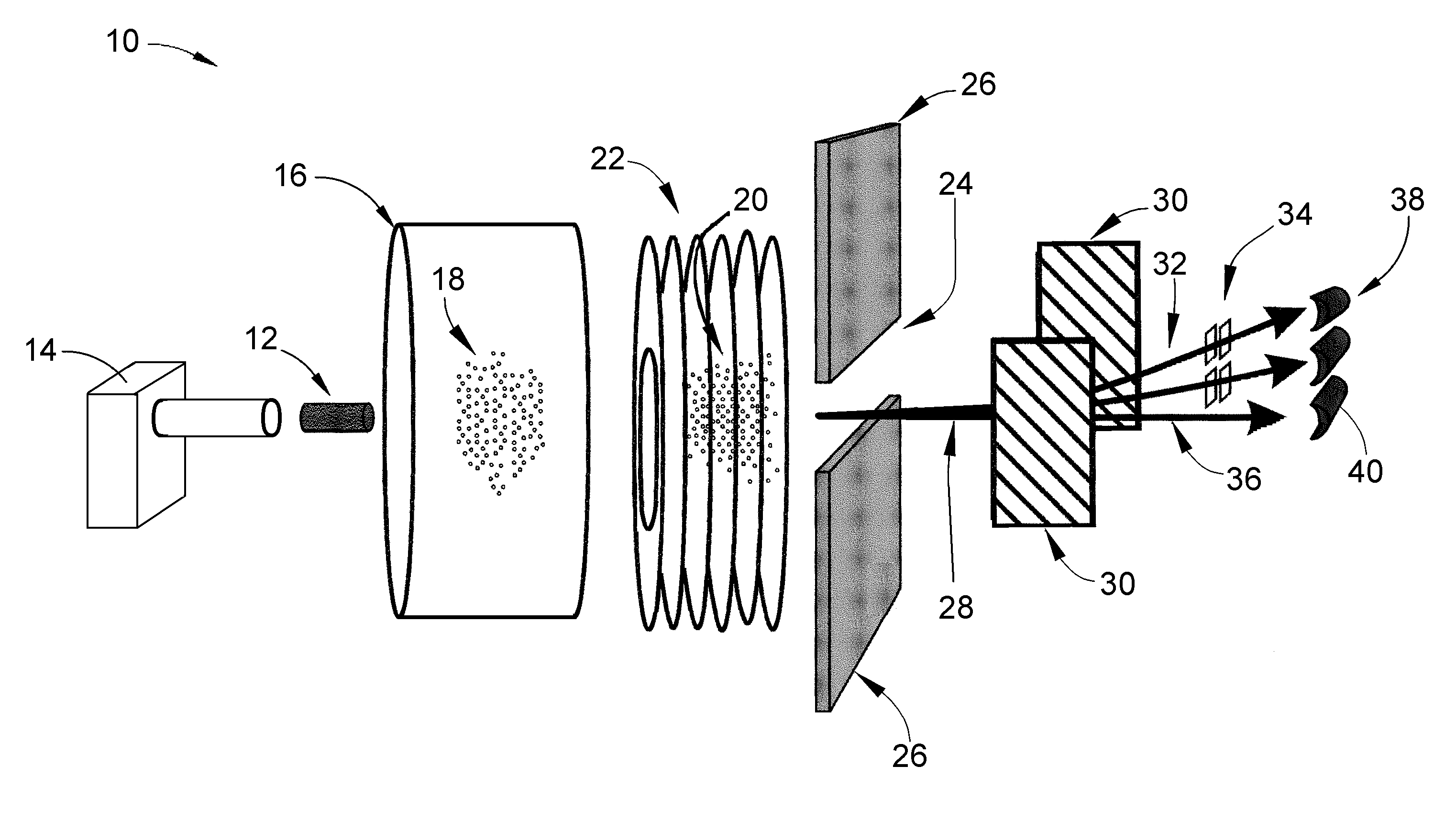
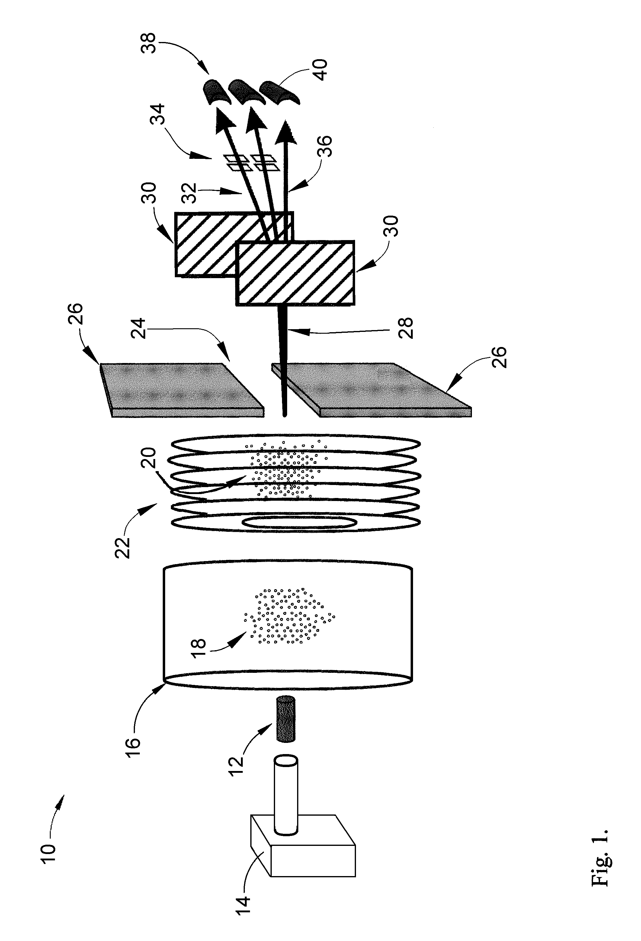
[0018]The present invention involves a process in which a body or slug of material, such as cored rock or formed minerals, is given a velocity and directed on a substantially linear path. This velocity may come from an electromagnetic catapult (also called a rail gun or a mass driver), or from a device employing stored mechanical energy such as a sling or catapult, or from a device using the rapid expansion of materials such as a cannon. Once the slug is given a velocity, it is heated very quickly to vaporize the material, a state in which molecular bonds within the matrix are broken to liberate individual elements as atoms. The heat for vaporization may come from concentrated sunlight or laser irradiation. The vaporized elements are now ionized using radio-frequency ionization and / or laser irradiation to form a plasma. Though the linear velocity of the slug is conserved by the ionized elements, the thermal expansion of the vaporization process will cause radial spreading of the mat...


PUM


Abstract

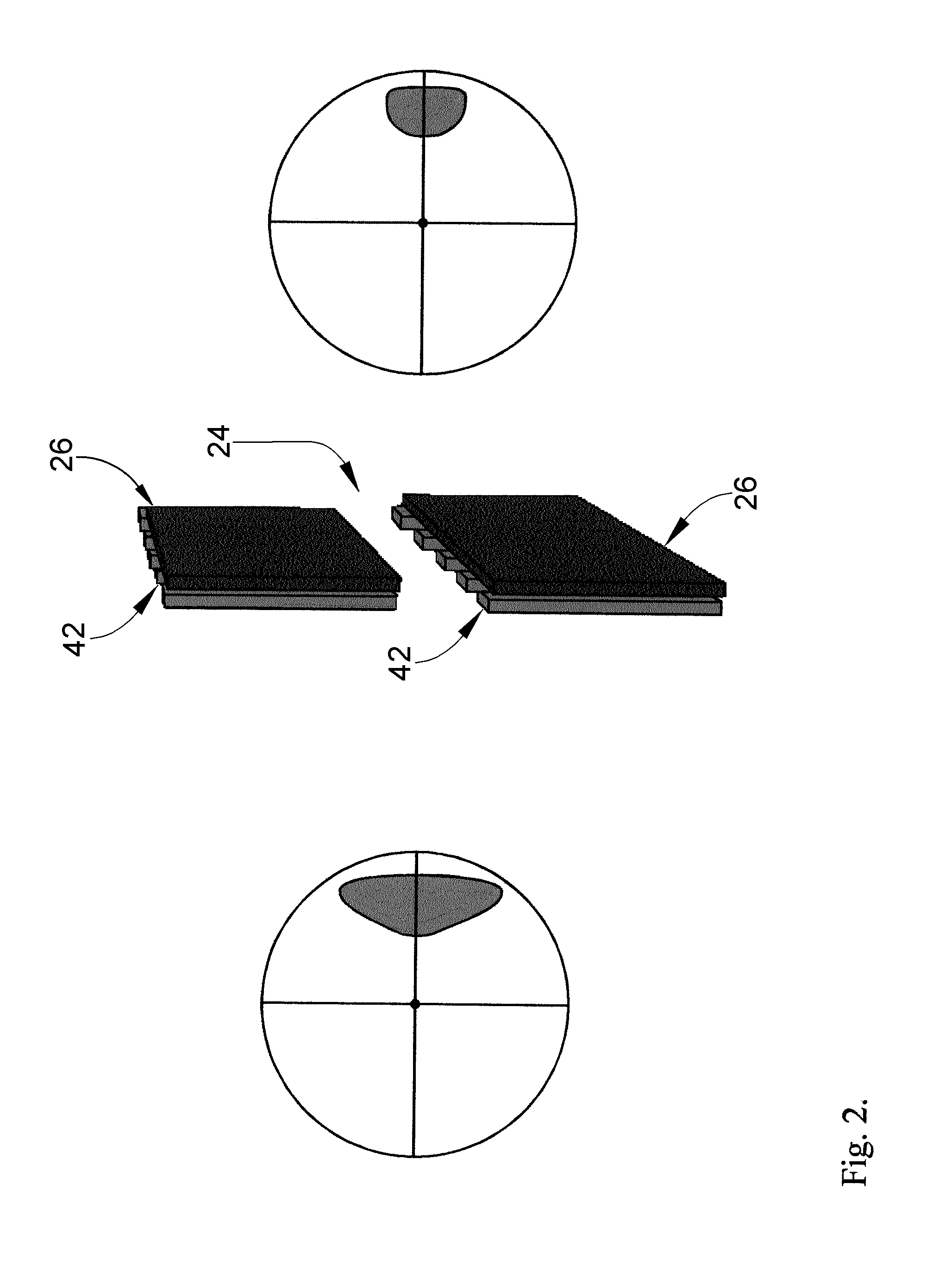
A process and apparatus for separating element isotopes in space by imparting a velocity and direction to a body of material along a substantially linear path, heating and vaporizing the body and ionizing the material thereof as it flows along the path to produce a first stream comprising ionized material, and then using at least one aperture to separate a first portion of the ionized material having a velocity transverse to the path that exceeds a predetermined transverse velocity limit while a second portion of the ionized material passes through the aperture and can be subsequently collected.

Description

CROSS REFERENCE TO RELATED APPLICATIONS[0001]This application claims the benefit of U.S. Provisional Application No. 60 / 521,201, filed Mar. 10, 2004.BACKGROUND OF THE INVENTION[0002]The present invention generally relates to the process of isotope separation, by which atoms of varying molecular weight can be differentiated.[0003]Commonly-owned U.S. Pat. No. 6,614,018 to Schubert discloses an apparatus and process for continuous isotope separation in microgravity using solar power. Generally, Schubert's apparatus has axial symmetry and utilizes magnetic beam confinement to perform a continuous process in microgravity environments.[0004]Several subfields relate to apparatuses and processes of the type taught by Schubert. One subfield is mass spectroscopy, wherein a sample is ionized and sputtered from the matrix being studied through bombardment by another ion such as oxygen or argon. A sample analyzer segregates isotopes through the application of a magnetic field. As ions of charge ...

Claims


Application Information

Patent Timeline
Patent Type & Authority Patents(United States)
IPC IPC(8): B01D59/44H01J49/00
CPCB01D59/46
Inventor SCHUBERT, PETER J.
Owner SCHUBERT PETER J
Why Eureka
Eureka Blog
Learn More