Method and apparatus for operating traveling spark igniter at high pressure

a technology of spark igniter and high pressure, which is applied in the direction of spark plugs, mechanical devices, machines/engines, etc., can solve the problems of tsis, as for any spark plug, and the ignition system of the spark plug cannot be effective and practical, and achieve the problem of both the isolator and the electrod

Active Publication Date: 2008-12-23
KNITE INC
View PDF7 Cites 36 Cited by
  • Summary
  • Abstract
  • Description
  • Claims
  • Application Information

AI Technical Summary

Benefits of technology

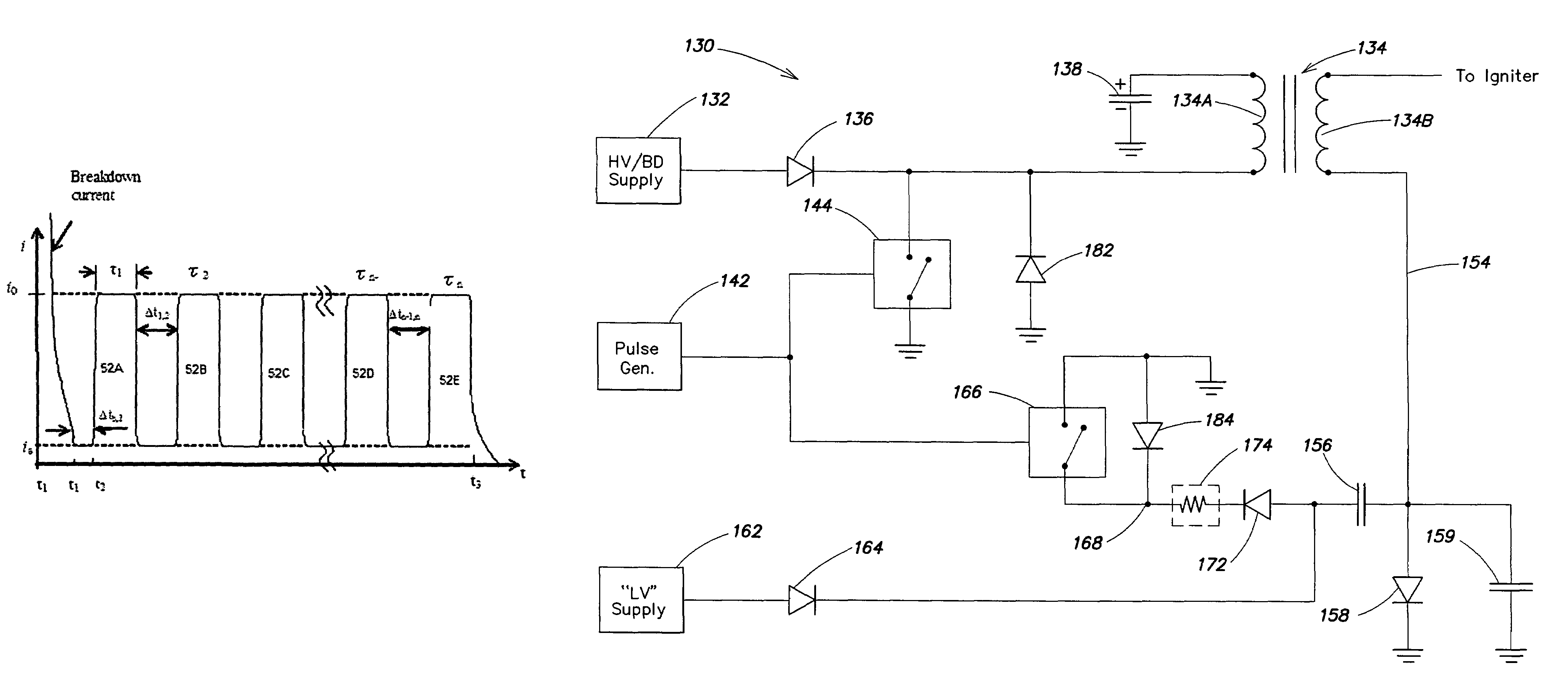
[0023]A fuel ignition method, comprising applying a high voltage to an igniter in the presence of a combustible fuel, said high voltage being of amplitude sufficient to cause breakdown to occur between the electrodes of the igniter, resulting in a high current electrical discharge in the igniter in an initiation region, and formation of a plasma kernel adjacent said initiation region; and following breakdown, applying to said electrodes a sequence of two or more relatively lower voltage follow-on pulses, whereby the plasma kernel is forced to move toward a free end of said electrodes by said follow-on pulses. The initiation region may be on or adjacent the surface of an isolator disposed between said electrodes. The igniter may be in an internal combustion engine. A current of the follow-on pulses for a gasoline-fueled internal combustion engine, may be between about 3 and 450 Amperes. Preferably, said method includes preventing total kernel recombination of the plasma prior to a follow-on pulse.

Problems solved by technology

To date, however, there has not been an effective and practical ignition system for such engines.
This creates problems for TSIs, as for any spark plug.
The higher breakdown voltage causes problems for both the isolator and the electrodes.
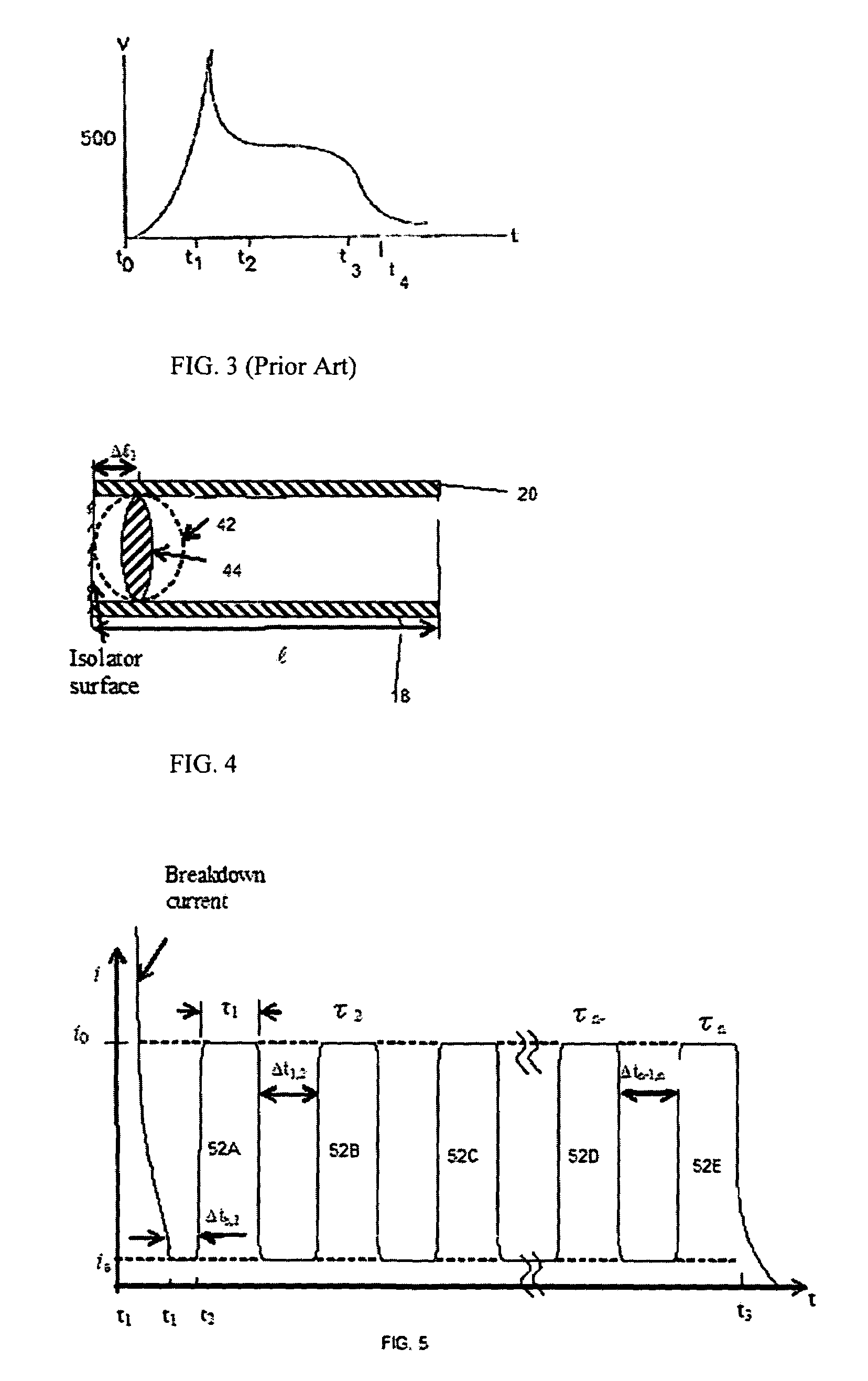
Such rapidly rising current, though, creates not only a very high temperature plasma, but also a powerful shock wave in the vicinity of the surface of the isolator.
The larger the current, the more rapid the plasma expansion and the resulting shock wave.
These combined effects can cause deformation and / or breakage of the isolator.
Additionally, the high current produces very rapid erosion of the electrodes in the vicinity of the isolator surface, where they are attacked by the high current, thermal heating and thermionic emission that results therefrom.
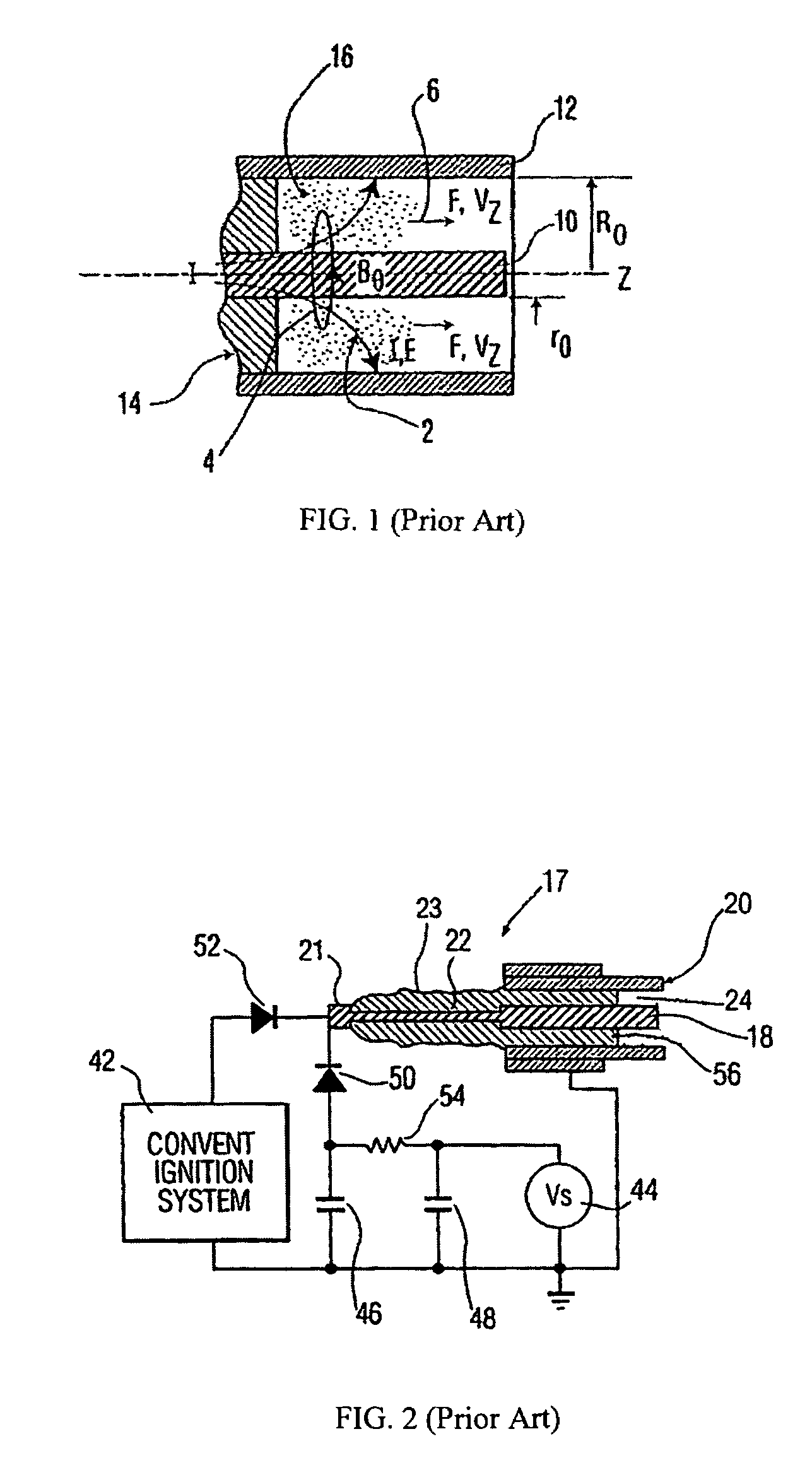
Similar problems have been manifest with igniters based on the University of Texas “railplug” design which generates a Lorentz force in a plasma traveling along a high aspect ratio discharge gap (as contrasted with a TSI, which has a low aspect ratio discharge gap).
Although both the railplug and the TSI generate significant plasma motion at relatively low pressures, when the combustion chamber pressure is increased to a high pressure, the plasma behaves differently and it is this difference in behavior that leads to unsatisfactory results.
So, in addition to the other problems, there is a loss in motive force applied to the plasma.
Overall, there is a reduction in plasma motion as compared with the lower pressure environments, and dramatically increased electrode wear at the arc attachment points.

Method used


Image

  • Method and apparatus for operating traveling spark igniter at high pressure
  • Method and apparatus for operating traveling spark igniter at high pressure
  • Method and apparatus for operating traveling spark igniter at high pressure

Examples


Embodiment Construction

[0044]Herein are explained in greater detail numerous aspects of the invention; the problems addressed by the invention, in greater detail than above; and a single embodiment of an example of an ignition circuit for practicing aspects of the invention.

[0045]According to a first aspect, there will be shown a method of operating an igniter in an internal combustion engine, comprising: applying a high voltage to electrodes of the igniter, said high voltage being of amplitude sufficient to cause electrical discharge breakdown to occur between the electrodes, in an initiation region (e.g., over a surface of an isolator) between the electrodes, resulting in a high current electrical discharge in the igniter, and formation of a plasma kernel in an air or fuel-air mixture adjacent said surface; and following breakdown, applying to said electrodes (preferably a simmer current) and a sequence of one or more lower voltage and lower current pulses, whereby the plasma kernel is forced to move to...


PUM


Abstract

An ignition circuit and a method of operating an igniter (preferably a traveling spark igniter) in an internal combustion engine, including a high pressure engine. A high voltage is applied to electrodes of the igniter, sufficient to cause breakdown to occur between the electrodes, resulting in a high current electrical discharge in the igniter, over a surface of an isolator between the electrodes, and formation of a plasma kernel in a fuel-air mixture adjacent said surface. Following breakdown, a sequence of one or more lower voltage and lower current pulses is applied to said electrodes, with a low “simmer” current being sustained through the plasma between pulses, preventing total plasma recombination and allowing the plasma kernel to move toward a free end of the electrodes with each pulse.

Description

RELATED APPLICATIONS[0001]This application claims the benefit, under 35 USC 119(e) of prior U.S. provisional patent application Ser. No. 60 / 672892, filed Apr. 19, 2005, having the same title and assignee, and which is incorporated by reference in its entirety herein.BACKGROUND OF INVENTION[0002]1. Field of Invention[0003]This invention relates to the fields of plasma generation, ignitions, and internal combustion (IC) engines. In particular, it relates, but is not limited, to ignition methods and ignition apparatus for use therein; and, specifically, to ignition methods and apparatus for various applications, including but not limited to, high pressure engines. More particularly, some aspects relate to the delivery of discharge current to traveling spark igniters in order to maximize their performance and longevity, especially in internal combustion engines operating at high pressures.[0004]2. Discussion of Related Art[0005]For a variety of reasons, there is interest today in increa...

Claims


Application Information

Patent Timeline
Patent Type & Authority Patents(United States)
IPC IPC(8): F02P3/02
CPCF02P3/0815H05H1/48H01T13/50F02P9/007F02P3/08F02P23/04F02P3/0807
Inventor SUCKEWER, ARTUR P.SUCKEWER, SZYMONSELMON, III, FREDERICK H.
Owner KNITE INC
Why Eureka
Try Eureka