Multitarget tracking antispoofing receiver

a receiver and multi-target technology, applied in the field of gps receivers, can solve the problems of inability to address methods, limitations regarding the size of the field of view, and existing methods are not well positioned to function properly, so as to hinder the ability to interfere, maintain the ability to.

Active Publication Date: 2008-12-30
THE AEROSPACE CORPORATION
View PDF19 Cites 26 Cited by
  • Summary
  • Abstract
  • Description
  • Claims
  • Application Information

AI Technical Summary

Benefits of technology

[0027]The tracking receiver has a very large field of view and operates to track multiple concurrent signals in the field of view, one of which may be a desired target signal the others of which may be spoofing, undesired, jamming, or interfering signals. The breadth of the field of view allows the receiver to wait until the signals are resolved before making a decision as to which is the target signal and which are spoofing signals. Adjusting the position of the window field of view is critical to maintaining the ability to detect the signals and distinguish between the signals. Adjusting the position of the window is accomplished using a large field of view and inertial measurement unit (IMU) data. In the case where there is an interfering signal, the tracking receiver maintains track on the target signal. The tracking receiver tracks code phase and carrier frequency and power. The greater power of the spoofer is a distinguishing characteristic between the two signals and hence actually hinders its ability to interfere.
[0028]The tracking receiver utilizes an architecture that can be applied to many tracking systems including ultratight system. Conventional multitarget tracking algorithms are utilized to distinguish targets that might cross over in the code and carrier space. Consistency checks between the signals classified as satellite signals can be performed. Consistency checks can be employed in conjunction with directional techniques for tracking multiple signals. The massive correlator chips can be used as an enabling technology to determine the context about the trajectory and to properly classify signals that cross over each other. All detected signals can be tracked, and information can be kept regarding the dimensionality of the object as to how many signal types, power, direction, and motion in the code and carrier space, with compatibility with the IMU processing. Multitarget tracking algorithms are utilized to resolve the tracks of the signals.
[0029]When signal tracks have been sufficiently resolved, tracking information is fed to a prefilter and ultimately to the navigation filter. With a large number of correlators available to us, we have a significant field of view that enables continuous measurements of all signals of interest. The IMU information allows for a narrow gate for the true signal. The crossing of tracks can be anticipated and resolved without losing track on a desired object. The multitarget tracker is also able to track the spoofer's trajectory fairly well. The spoofer tracks have a greater process noise than the true signal because their motion in the code and carrier space is not tied to a physical phenomenon and hence there is no possibility of an aiding sensor trajectory for the spoofer. The tracking receiver has a large field of view for tracking multiple signals using signal characteristic. As such, the tracking receiver can track multiple signals, and maintain a lock on a target signal, even in the presence of cross over spoofing signals that cross over the target signal. These and other advantages will become more apparent from the following detailed description of the preferred embodiment.

Problems solved by technology

Spoofing is when the receiver is drawn off tracking of the target signal and disadvantageously tracks the spoofing signal when the receiver is designed to track only one signal in the field of view.
That is, existing methods track only one signal and for this reason, existing methods are not well positioned to function properly in the presence of a spoofer.
These methods offer some improvement by reducing the bandwidth but still suffer from limitations regarding the size of the field of view and the fact that the device does not track multiple signals.
The existing methods do not address the problems that occur when the spoofing signals are within the received bandwidth, instead a narrowing of the bandwidth is performed so that the spoofing signals will either not be within the signal space at all, or if inside the signal space, the spoofing signals will not remain within the signal space long enough to disturb the navigation solution.
The design of tracking loop transfer functions is compromised to meet two conflicting requirements.
On the other hand, if the tracking loop is too sluggish because of a low operating bandwidth, the tracking loop cannot track the dynamics of the relative motion often caused by vehicular acceleration.
If the tracking loop fails to drive the error signal to zero, the amount of error that remains uncorrected is a measurement error that is fed into the navigation-processing algorithm as an unmodeled pseudorange and pseudorange rate measurement error.
This time-correlated unmodeled pseudorange and pseudorange rate measurement error limits the allowable update rate of the navigation Kalman filter, because the assumption made in the Kalman filter processing is that the measurement errors are uncorrelated in time.
This update rate limitation has traditionally limited the allowable processing rate of GPS measurements from an aided tracking loop to about one hertz.
But, all of this I and Q information is not necessarily used to improve the pseudorange and pseudorange rate measurement accuracy due to the fading memory of the tracking loop having a lower but limited bandwidth.
Aided tracking loops have a narrow bandwidth but still suffer from an inability to track multiple signals and the narrow field of view.
This out of lock condition is due to the nonlinearity of the correlation process and the use of linear loop designs that are only valid for small error conditions.
Hence, one tracking loop may lose lock due to a low signal-to-noise ratio even though other GPS channels are being normally tracked.
The information from the other good channels is not used in the inoperative channel that may be out of lock due to a marginal signal to noise ratio that is insufficient to maintain lock.
Yet these measurements are not independent because these measurements are received by only one antenna.
Prior tightly coupled systems are limited by the use of Costas carrier loops for determining twenty-millisecond bit boundary data without required a priori knowledge of the data bits.
These approaches suffer from the requirement for huge processor throughput because the Kalman filter, that may have twenty or more state variables, must operate at several tens of Hertz.
With unlimited integration Kalman filter processor throughput, the integration Kalman filter could be operated at extremely high rates with no loss of optimality due to time correlated tracking loop errors.
The advanced tracking loops, similar to vector loops, still have a narrow field of view for tracking only one signal and do not allow for the concurrent tracking of multiple signals.
In traditional receivers, the integrate-and-dump process is limited to twenty-milliseconds due to the potential change of a data bit in the navigation message.
Although data stripping has been demonstrated to work, the results have been somewhat disappointing relative to predicted improvements and the logistics of determining the future navigation data message is cumbersome.
When two signals cross it is possible for them to interfere with each other and give unusual measurements that do not fit either track.
The crossing of spoofing signals cannot be predicted and no context is available for the resolution of various tracks.
In addition, most existing methods disadvantageously use a narrow field of view when tracking in the field of view.

Method used


Image

  • Multitarget tracking antispoofing receiver
  • Multitarget tracking antispoofing receiver
  • Multitarget tracking antispoofing receiver

Examples


Embodiment Construction

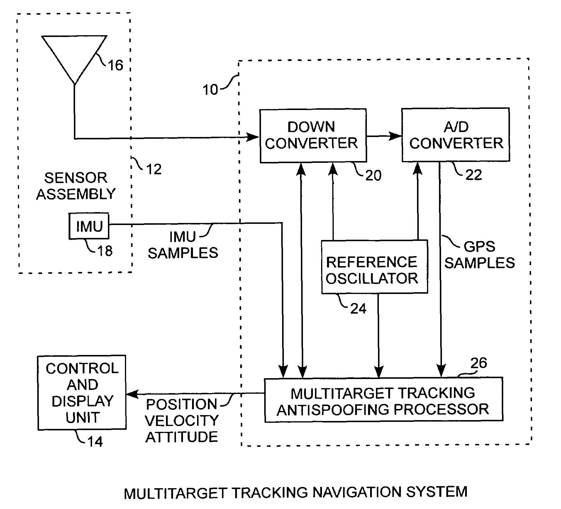
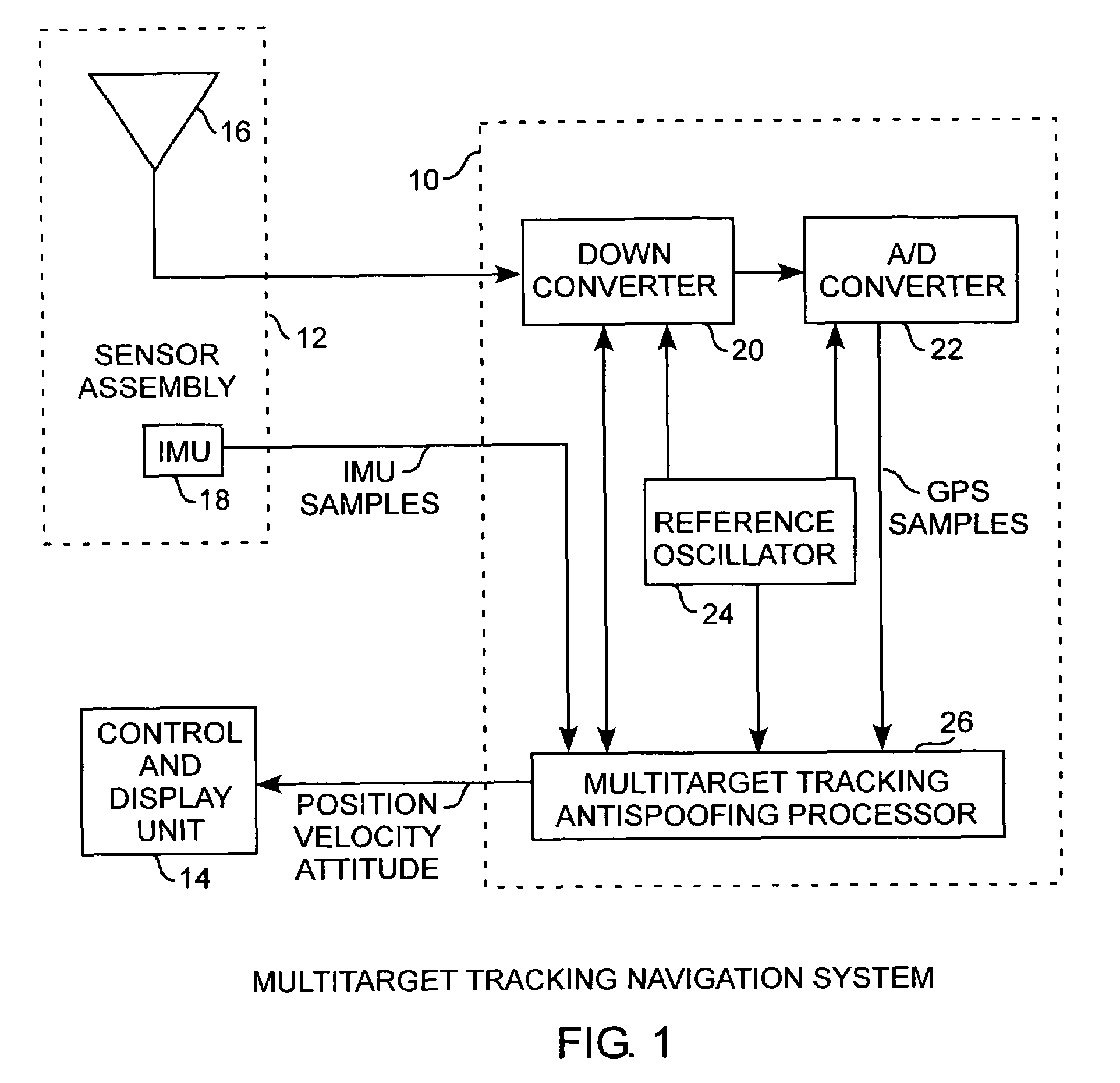
[0036]An embodiment of the invention is described with reference to the figures using reference designations as shown in the figures. Referring to FIG. 1, a global positioning system (GPS) inertial navigation system includes a navigation system 10 receiving GPS signals and inertial measurement unit samples from a sensor assembly 12 and provides position and velocity data to a control and display unit 14. The navigation system 10 functions as a GPS inertial navigation system tracking GPS signals from a plurality of in-view satellites, not shown. The sensor assembly 12 includes an antenna 16 for receiving and providing received GPS signals and includes an inertial measurement unit (IMU) 18 providing the IMU sample signals, both of which are communicated to the navigation system 10. In the preferred form, the IMU 18 may be a microelectromechanical system (MEMS) IMU embedded in the antenna 16. The navigation system 10 includes a downconverter 20 for frequency downconversion of the recei...


PUM


Abstract

A multitarget tracking antispoofing receiver utilizes multitarget tracking algorithms and multiple correlators for tracking signals of interest in a field of view about a nominal trajectory of a desired true signal for tracking targets within the code phase and carrier frequency signal space so as to predict when true and spoof signals will cross paths in the signal space without spoofing with loss of tracking of the desired signal so that true tracking of a desired target is maintained in the presence of a spoofing signal moving along a spoofing signal track and crossing a true path of the true signal.

Description

FIELD OF THE INVENTION[0001]The invention relates to the field of GPS receivers. More particularly, the present invention relates to GPS receivers for tracking desired signals of a desired target and for tracking undesired signals of a spoofing target for maintaining tracking of the desired target.BACKGROUND OF THE INVENTION[0002]A spoofer signal is able to draw a receiver off of track of the true signal by sending a bogus signal, typically of higher power, across a target signals path in the signal space in code phase and carrier frequency. When there is a sufficiently slow divergence of the true and spoofer signals at the point where the spoofer signal and target signal cross over each other in the signal space, the signal tracker may end up following the more powerful spoofer signal. Spoofing is when the receiver is drawn off tracking of the target signal and disadvantageously tracks the spoofing signal when the receiver is designed to track only one signal in the field of view. ...

Claims


Application Information

Patent Timeline
Patent Type & Authority Patents(United States)
IPC IPC(8): G01S1/00G01C21/00H04B1/00G01S19/21G01S19/26G01S19/29G01S19/30
CPCG01S19/21G01S19/215G01S19/26G01S19/29G01S19/30
Inventor LILLO, WALTER E.SCULLY, KEVIN J.NEALY, CARLTON D.
Owner THE AEROSPACE CORPORATION
Why Eureka
Try Eureka