Pressure wave generator and process for manufacturing the same

a technology of pressure wave generator and process, which is applied in the direction of mechanical vibration separation, instruments, loudspeakers, etc., can solve the problems of damage to the thermal insulation layer b>2/b>, and achieve the effects of reducing thermal stress acting on the heating conductor, generating stably, and prolonging the operating life of the pressure wave generator

Inactive Publication Date: 2009-01-06
MATSUSHITA ELECTRIC WORKS LTD
View PDF5 Cites 72 Cited by
  • Summary
  • Abstract
  • Description
  • Claims
  • Application Information

AI Technical Summary

Benefits of technology

[0018]According such a configuration, in the pressure wave generator comprising the substrate, the thermal insulation layer of the porous material which is formed on the face of the substrate in thickness direction, and the heating conductor of thin film formed on the thermal insulation layer, and wherein the temperature of the heating conductor varies depending on waveforms of electric input to the heating conductor, and the pressure wave generator generates pressure waves by heat exchange between the heating conductor and an atmosphere such as air, when the thickness at the center of the thermal insulation layer in width direction is used as the reference thickness, and it is assumed that distribution of thickness of thermal insulation layer in the width direction is averaged with the reference thickness, the porosity in the outer peripheral portion of the thermal insulation layer is made smaller than porosity in the center portion of the thermal insulation layer. Thus, even when it is used in the atmosphere in a long term, and thereby, compression stress may occur because the volume of the thermal insulation layer expands due to chemical reaction such as oxidation of the thermal insulation layer, the compression stress can be dispersed by the outer peripheral portion of the thermal insulation layer where the porosity is made smaller. In other words, by making the porosity in the outer peripheral portion of the thermal insulation layer smaller, a number of immovable points in the outer periphery of the thermal insulation layer restricted by the substrate is increased and the positions of the points are dispersed in comparison with the conventional pressure wave generator, and thereby, the compression stress, which may be concentrated in the peripheral portion of the thermal insulation layer, can be dispersed. Consequently, it is possible to reduce the possibility of generation of cracks in the thermal insulation layer and to prevent occurrence of fracture of the heat conductor due to cracks of the thermal insulation layer. Furthermore, the fracture of the pressure wave generator can be prevented, and thereby ultrasonic wave can be generated stably in a long term.
[0020]In such a case, even when the volume of the thermal insulation layer is expanded due to chemical reaction such as oxidation of the thermal insulation layer in the long term use in the atmosphere, the compression stress, which was concentrated at a portion where the outer periphery of the thermal insulation layer contacts with the surface of the substrate in the conventional pressure wave generator, can be dispersed along the outer peripheral surface (such as an inclined face) of the thermal insulation layer in the outer peripheral portion of the thermal insulation layer. Consequently, it is possible to reduce the possibility of generation of cracks in the thermal insulation layer and to prevent occurrence of fracture of the heat conductor due to cracks of the thermal insulation layer. Furthermore, the fracture of the pressure wave generator can be prevented, and thereby ultrasonic wave can be generated stably in a long term.
[0021]Still furthermore, heat quantity radiated along the thickness direction of the substrate in the outer peripheral portion of the thermal insulation layer becomes larger than the heat quantity radiated along the thickness direction of the substrate in the center portion, so that mechanical strength of the thermal insulation layer and the heating conductor in the vicinity of the boundary between the substrate and the thermal insulation layer can be increased. Consequently, it is possible to prevent fractures of the thermal insulation layer and the heating conductor due to stress can be prevented. In addition, it is no need to change the materials and / or compositions of them, so that the pressure wave generator can be manufactured easily.
[0028]In this way, when the mean heat conductivity is designated by the symbol α in and the mean volume heat capacity is designated by the symbol Cin in the thickness direction of the inner portion than the outer periphery of the heating conductor, and the mean heat conductivity is designated by the symbol α out and the mean volume heat capacity is designated by the symbol Cout in the thickness direction of the outer portion than the outer periphery of the heating conductor, the condition of α in×Cin<α out×Cout is satisfied and the value of α in×Cin becomes larger approaching to outside in the vicinity of the boundary between the inner portion and the outer portion. Thus, the heat quantity radiated along the thickness direction of the substrate in the outer peripheral portion of the thermal insulation layer becomes larger than the heat quantity radiated along the thickness direction of the substrate in the center portion, so that the thermal stress acting on the heating conductor can be reduced in comparison with that of the conventional pressure wave generator. Thereby, fracture of the heating conductor due to the thermal stress hardly occurs in comparison with the conventional pressure wave generator, and thereby enabling longer operating life of the pressure wave generator. In other words, even when the thermal stress occurs due to expansion and contraction of the heating conductor corresponding to temperature rise and temperature fall of the heating conductor in the driving of the pressure wave generator, the heating conductor is rarely broken so that the ultrasonic can be generated stably in a long term.

Problems solved by technology

Thus, cracks occur in the vicinity of the point P1 of the thermal insulation layer 2 of the porous material, so that the thermal insulation layer 2 may be damaged.

Method used


Image

  • Pressure wave generator and process for manufacturing the same
  • Pressure wave generator and process for manufacturing the same
  • Pressure wave generator and process for manufacturing the same

Examples


first embodiment

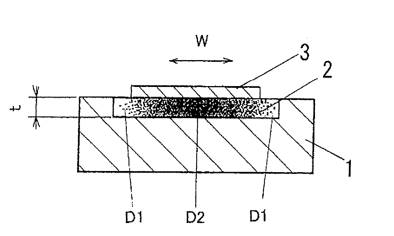
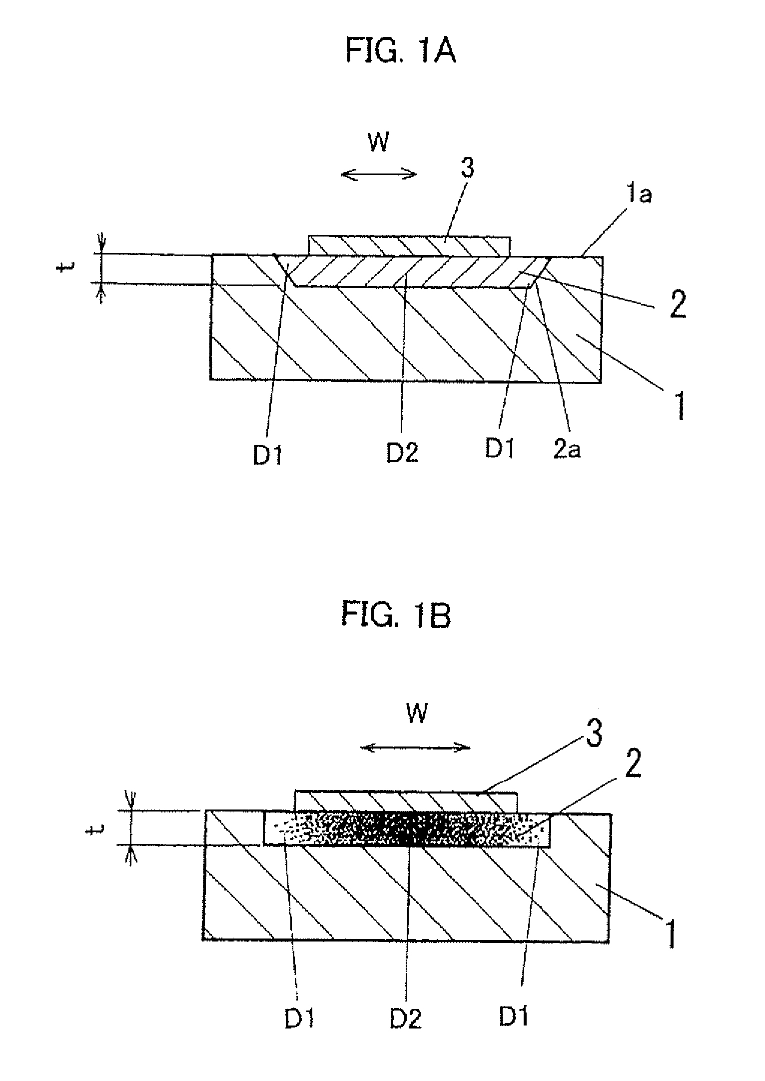
[0083]A first embodiment of the present invention is described. FIG. 1A is a sectional view showing an essential structure of a pressure wave generator in accordance with the first embodiment. As shown in FIG. 1A, the pressure wave generator comprises a substrate 1 which is made of, for example, a semiconductor substrate, a thermal insulation layer 2 of a porous material such as porous silicon layer which is formed on a surface (first surface) of the substrate 1 in thickness direction, and a heating conductor 3 of a thin film such as an aluminum thin film which is formed on the thermal insulation layer 2. Such pressure wave generator generates pressure waves by heat exchange between the heating conductor 3 and a medium such as air when the temperature of the heating conductor 3 varies corresponding to waveforms of electric input to the heating conductor 3.

[0084]In the pressure wave generator in accordance with the first embodiment, when it is assumed that distribution of the thickne...

second embodiment

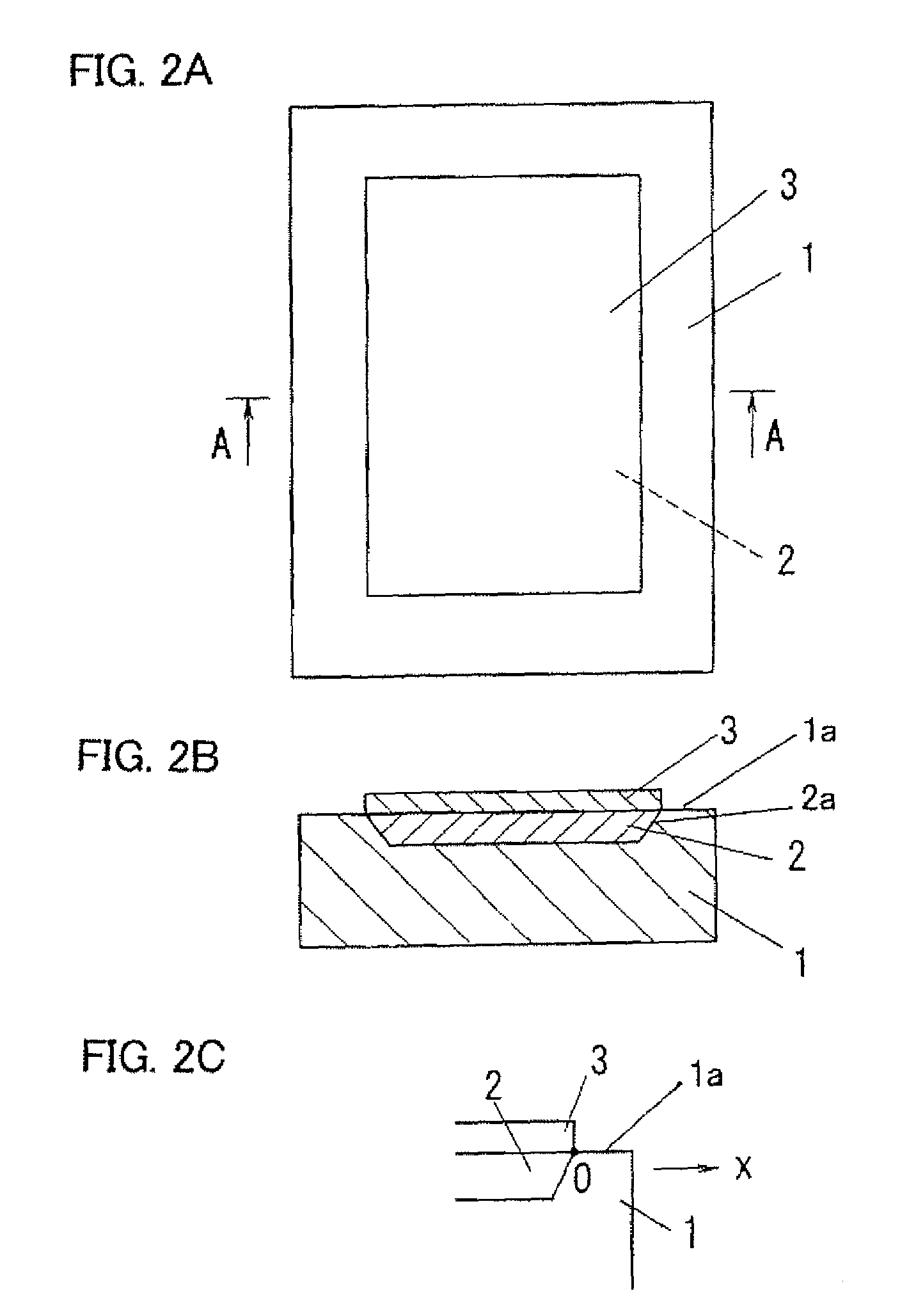
[0089]A first embodiment of the present invention is described. FIG. 2A is a plain view of a pressure wave generator in accordance with the second embodiment. FIG. 2B is an A-A sectional drawing in FIG. 2A.

[0090]As shown in FIG. 2B, the pressure wave generator of the second embodiment comprises a semiconductor substrate (substrate) 1 of p-type single crystalline silicon substrate, a thermal insulation layer 2 of porous silicon layer (porous material), which is formed inwardly to an inside of the semiconductor substrate 1 from a surface (first surface) 1a of the semiconductor substrate 1 in thickness direction thereof, and a heating conductor 3 of thin film (such as a metal thin film, for example, aluminum thin film) formed on the thermal insulation layer 2. As shown in FIG. 2A, a planar shape of the semiconductor substrate 1 is rectangular (for example, oblong), and planar shapes of the thermal insulation layer 2 and the heating conductor 3 are formed to rectangular (for example, ob...

third embodiment

[0117]Subsequently, a third embodiment of the present invention is described. Essential structure of the pressure wave generator of the third embodiment is the same as that of the above mentioned second embodiment, but different at a point of adopting an n-type single crystalline silicon substrate for the semiconductor substrate 1 from the second embodiment. Thus, description and illustration of the configuration of the pressure wave generator is omitted, but only the process of manufacture of the pressure wave generator is described with reference to FIGS. 10A to 10C.

[0118]As show in FIG. 10A, an energizing electrode 4 used for anodization processing is formed on an entire surface of a second surface 1b in thickness direction of a semiconductor substrate 1 of n-type silicon substrate. As for the energizing electrode 4, it is possible that an electric conductive layer is formed on the second surface 1b of the semiconductor substrate 1 with using, for example, by sputtering method or...


PUM

PropertyMeasurementUnit
Young's modulusaaaaaaaaaa
humidityaaaaaaaaaa
temperatureaaaaaaaaaa

Abstract

Even when compression stress is generated because a volume of a thermal insulation layer 2 is expanded due to oxidized by oxygen in the air, occurrence of cracks and fractures of the thermal insulation layer and a heating conductor 3 caused by the cracks are prevented by dispersing the compression stress. A pressure wave generator comprises a substrate 1, the thermal insulation layer 2 of porous material which is formed on a surface of the substrate 1 in thickness direction, and the heating conductor 3 of thin film formed on the thermal insulation layer 2, and generates pressure waves by heat exchange between the heating conductor 3 and a medium. When a thickness at the center of the thermal insulation layer 2 in width direction W is used as a reference thickness, and it is assumed that distribution of thickness of thermal insulation layer in the width direction is averaged with the reference thickness, porosity in an outer peripheral portion of the thermal insulation layer is made smaller than porosity in the center portion. By making the porosity in the outer peripheral portion of the thermal insulation layer 2 smaller, a number of immovable points on the outer periphery of the thermal insulation layer 2 restricted by the substrate 1 is increased and the positions of them are dispersed, so that the compression stress compressed in the outer peripheral portion of the thermal insulation layer 2 can be dispersed.

Description

TECHNICAL FIELD[0001]The present invention relates to a pressure wave generator for generating pressure waves such as acoustic waves for speaker, ultrasonic sounds or single pulse compressional wave and a process for manufacturing the same.BACKGROUND ART[0002]An ultrasonic wave generator utilizing mechanical vibrations of piezoelectric effect is conventionally known widely. In the ultrasonic wave generator utilizing mechanical vibrations, electrodes are provided on both sides of a crystal of piezoelectric material such as barium titanate, and electric energy is supplied between both electrodes so that mechanical vibrations are generated. Thus, ultrasonic waves are generated with vibrating medium such as air. The ultrasonic wave generator utilizing mechanical vibrations, however, has inherent resonance frequency, so that frequency bandwidth of ultrasonic waves generated thereby is narrower. In addition, the ultrasonic wave generator is easily affected by outside oscillation or drift ...

Claims


Application Information

Patent Timeline
Patent Type & Authority Patents(United States)
IPC IPC(8): B06B1/00H04R23/00B06B1/02
CPCB06B1/02H04R23/002H04R31/003H04R2201/029
Inventor WATABE, YOSHIFUMIHONDA, YOSHIAKI
Owner MATSUSHITA ELECTRIC WORKS LTD
Why Eureka
Try Eureka