Catheter based balloon for therapy modification and positioning of tissue

a catheter and balloon technology, applied in the field of catheters, can solve the problems of cell death and tissue necrosis, etc., and achieve the effect of blocking the exposure of sensitive surrounding tissues

Inactive Publication Date: 2009-01-13
ACOUSTIC MEDSYST +1
View PDF34 Cites 57 Cited by
  • Summary
  • Abstract
  • Description
  • Claims
  • Application Information

AI Technical Summary

Benefits of technology

[0036]Another object of the invention is to provide an apparatus and method of blocking

Problems solved by technology

For exposures at comparatively longer times or higher temperatures, cellular repair mechanisms can no longer keep up or lose function due to the thermal damage of key enzymes, and cell death and tissue necrosis will occur within 3 to 5 days.
These thermal effects are lethal and immediate, producing thermally coagulated (dead) tissue.
However, the efficacy of these treatment modalities may be limited due to inadequacy in protecting sensitive non-targeted tissues or adequately treating a large enough of a volume of tissue.
Presently, treating the prostate gland with heat is problematic.
If properly positioned within the prostatic urethra, these devices can thermally destroy a region within the center of the prostate, which leads to a reduction of BPH symptoms.
Although moderately effective for treatment of BPH, these devices are not effective for treating prostate cancer, which mostly involves tissues away from the urethra in the posterior portion of the gland, often adjacent to critical nerves and the rectum.
In order to treat large distances from the urethra, higher amounts of energy and greater temperatures are required, leading to damage of the rectum or surrounding non-targeted tissues.
Transrectal focused ultrasound devices (HIFU) offer some spatial contro

Method used


Image

  • Catheter based balloon for therapy modification and positioning of tissue
  • Catheter based balloon for therapy modification and positioning of tissue
  • Catheter based balloon for therapy modification and positioning of tissue

Examples


Embodiment Construction

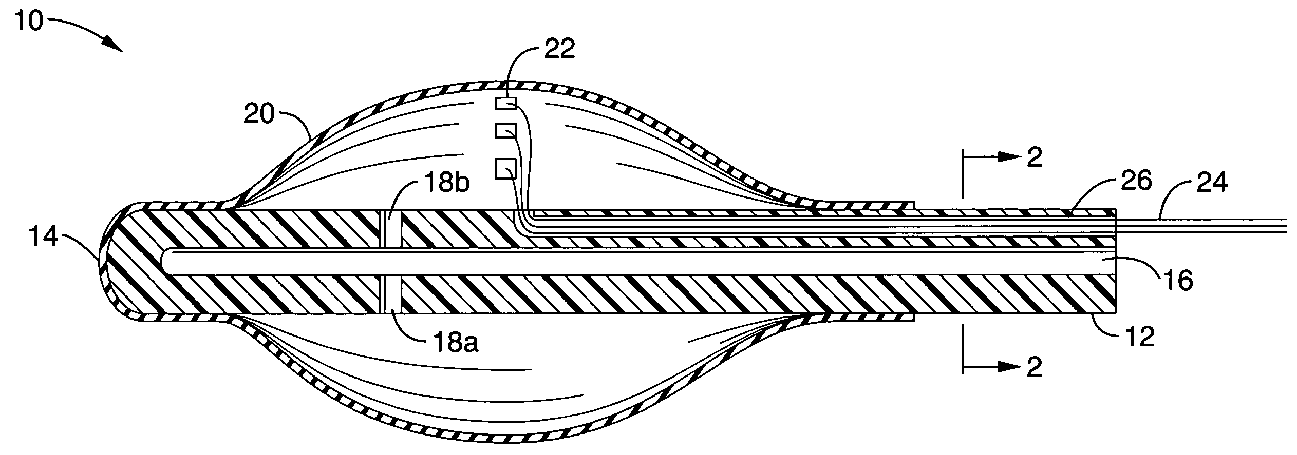
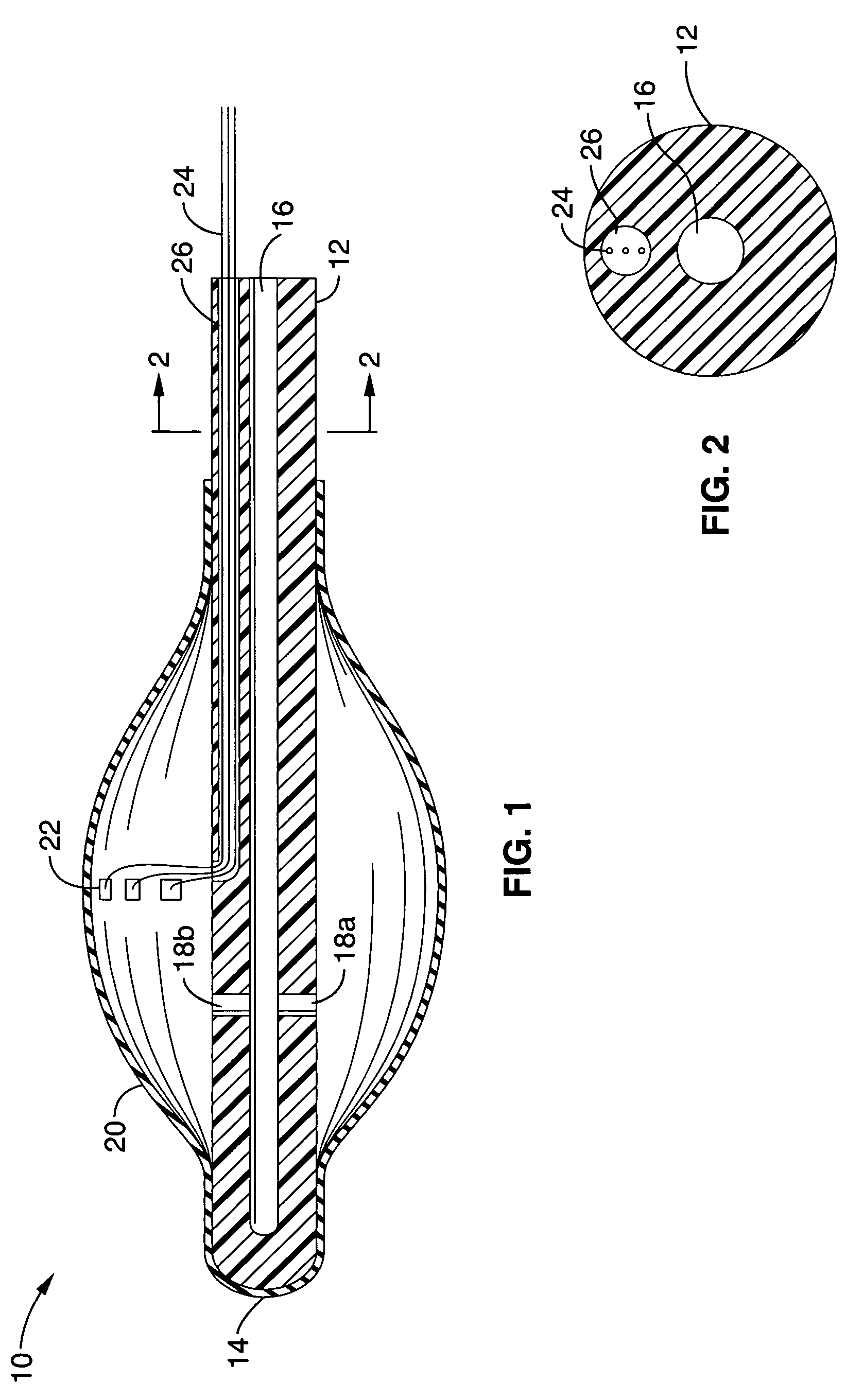
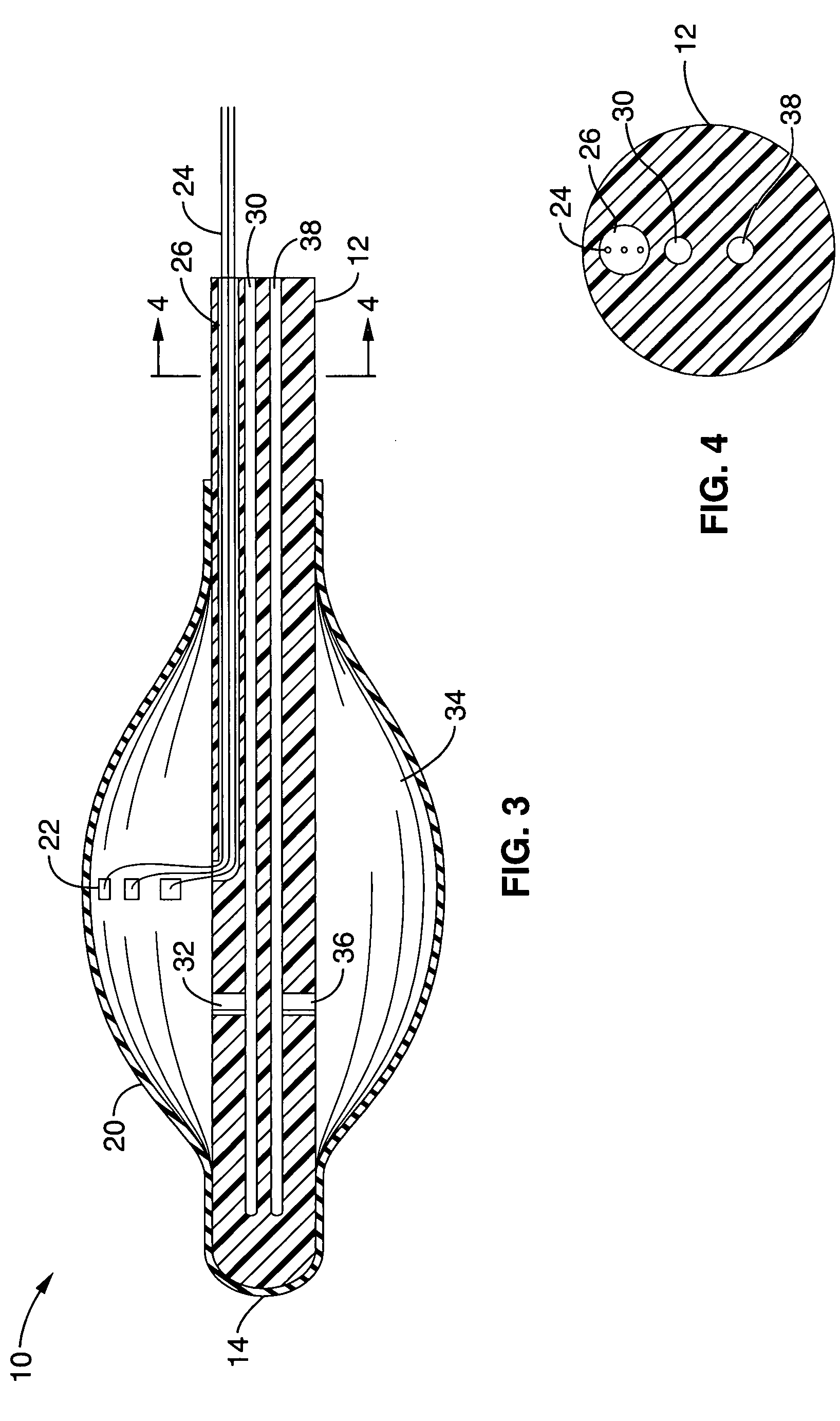
[0053]Referring more specifically to the drawings, for illustrative purposes the present invention is embodied in the apparatus and methods generally shown in FIG. 1 through FIG. 10. It will be appreciated that the apparatus may vary as to configuration and as to details of the parts, and that the methods may vary as to the specific steps and sequence, without departing from the basic concepts as disclosed herein.

[0054]Referring first to FIG. 1 and FIG. 2, the invention comprises a positioning catheter 10 with a catheter shaft 12 and tip 14 constructed for insertion into the body of a patient. The catheter shaft 12 and tip 14 may alternatively be configured to be inserted into tissue using a separate needle introduction catheter that is removed after insertion and provides protection to the components of the device during insertion. The apparatus may be used interstitially as well as laproscopically or endoscopically during procedures in the joints, abdomen, esophagus or uterus / cerv...


PUM


Abstract

An apparatus and method for shielding non-target tissues and organs during thermotherapy, brachytherapy or other treatment of a diseased target tissue. The apparatus includes a catheter shaft having input and output lumens and at least one inflatable balloon. A plurality of input lumens within the catheter shaft allows the passage of liquid or gas through an input port and into the interior of the balloon thereby inflating the balloon. The gas or liquid can then be cycled through the inflated balloon through an output port and output lumen and out of the catheter shaft. Temperature sensors or other sensors may be attached to the balloon or catheter to monitor temperature or other conditions at the treatment site. The catheter is positioned between the target tissue or organ and sensitive non-target tissues in proximity to the target tissue and inflated causing a physical separation of tissues as well as a physical shield.

Description

CROSS-REFERENCE TO RELATED APPLICATIONS[0001]This application is a divisional of U.S. application Ser. No. 10 / 020,583 filed on Dec. 14, 2001 now U.S. Pat. No. 6,746,465.STATEMENT REGARDING FEDERALLY SPONSORED RESEARCH OR DEVELOPMENT[0002]Not ApplicableINCORPORATION-BY-REFERENCE OF MATERIAL SUBMITTED ON A COMPACT DISC[0003]Not ApplicableNOTICE OF MATERIAL SUBJECT TO COPYRIGHT PROTECTION[0004]A portion of the material in this patent document is subject to copyright protection under the copyright laws of the United States and of other countries. The owner of the copyright rights has no objection to the facsimile reproduction by anyone of the patent document or the patent disclosure, as it appears in the United States Patent and Trademark Office publicly available file or records, but otherwise reserves all copyright rights whatsoever. The copyright owner does not hereby waive any of its rights to have this patent document maintained in secrecy, including without limitation its rights p...

Claims


Application Information

Patent Timeline
IPC IPC(8): A61M29/00A61B17/00A61B19/00A61F2/958A61M25/00
CPCA61M25/10A61B2017/00092A61B2017/00274A61B2017/00557A61B2018/00547A61B2019/4036A61M25/1011A61M2025/0037A61M2025/1013A61N5/1027A61N2005/1094A61B2090/0436A61B2018/005A61M29/02
Inventor DIEDERICH, CHRIS J.DEARDORFF, DANA L.
Owner ACOUSTIC MEDSYST
Why Eureka
Try Eureka