Method for fabricating rib-stiffened composite structures

Inactive Publication Date: 2009-01-20
THE UNITED STATES OF AMERICA AS REPRESETNED BY THE SEC OF THE AIR FORCE
View PDF5 Cites 53 Cited by
  • Summary
  • Abstract
  • Description
  • Claims
  • Application Information

AI Technical Summary

Benefits of technology

[0015]Other means of holding the expansion blocks in place can be utilized, such as vacuum pressure, friction, magnetic force, an over-wrap of a disposable material, or mechanical fasteners. Common to these means is that they allow the expansion blocks to freely expand to squeeze the ribs located in between complimentary expansion blocks with uniform pressure along their lengths, when the assembly exposed to the elevated temperature of the curing cycle. Therefore, i

Problems solved by technology

Thus, a large portion of the metallic material was wasted as scrap.
More particularly, moisture uptake is a well-known problem for honeycomb panels because water tends to become trapped in the hexagonal cells of the honeycomb and causes corrosion and softening of the composite face-sheets.
A second critical problem with structures made of honeycomb sandwich panels is that a large amount of time is required to cut and splice the honeycomb core to fit on shapes having complex curvatures, such as aircraft fuselages and rocket payload fairings.
This results in a high cost and a long lead-time for these structures.
Each of these previously disclosed methods of fabricating grid-stiffened structures has inherent problems that make it too costly and complex to be competitive with traditional sandwich panel structures.
For example, the hybrid expansion approach disclosed in U.S. Pat. No. 6,245,274 relies on a very complex base tool and matching set of expansion blocks.
Once the base tool is fabricated, it is very diff

Method used


Image

  • Method for fabricating rib-stiffened composite structures
  • Method for fabricating rib-stiffened composite structures
  • Method for fabricating rib-stiffened composite structures

Examples


Embodiment Construction

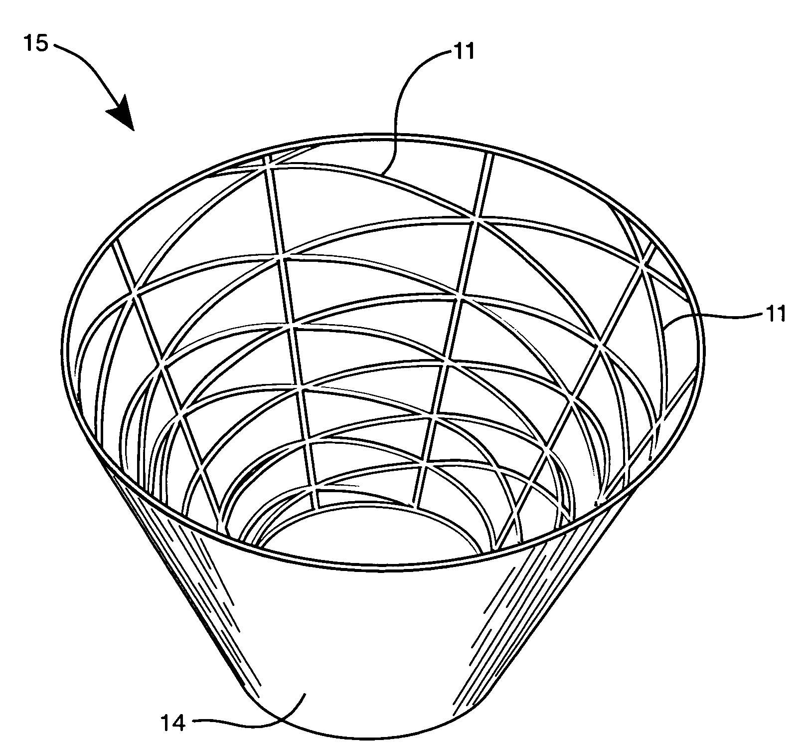
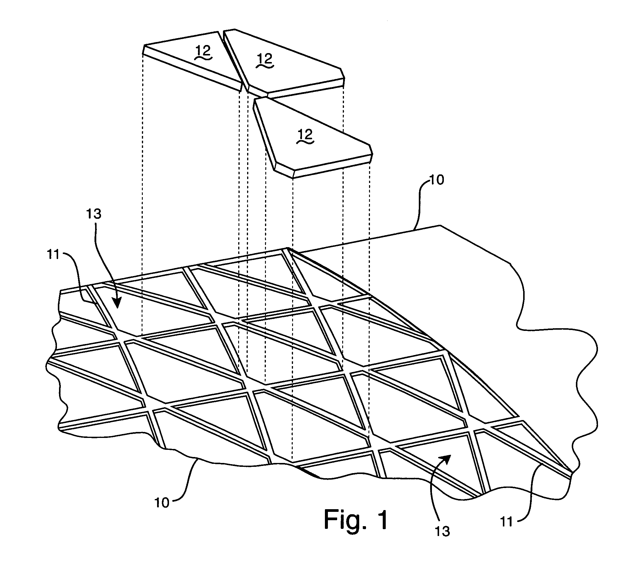
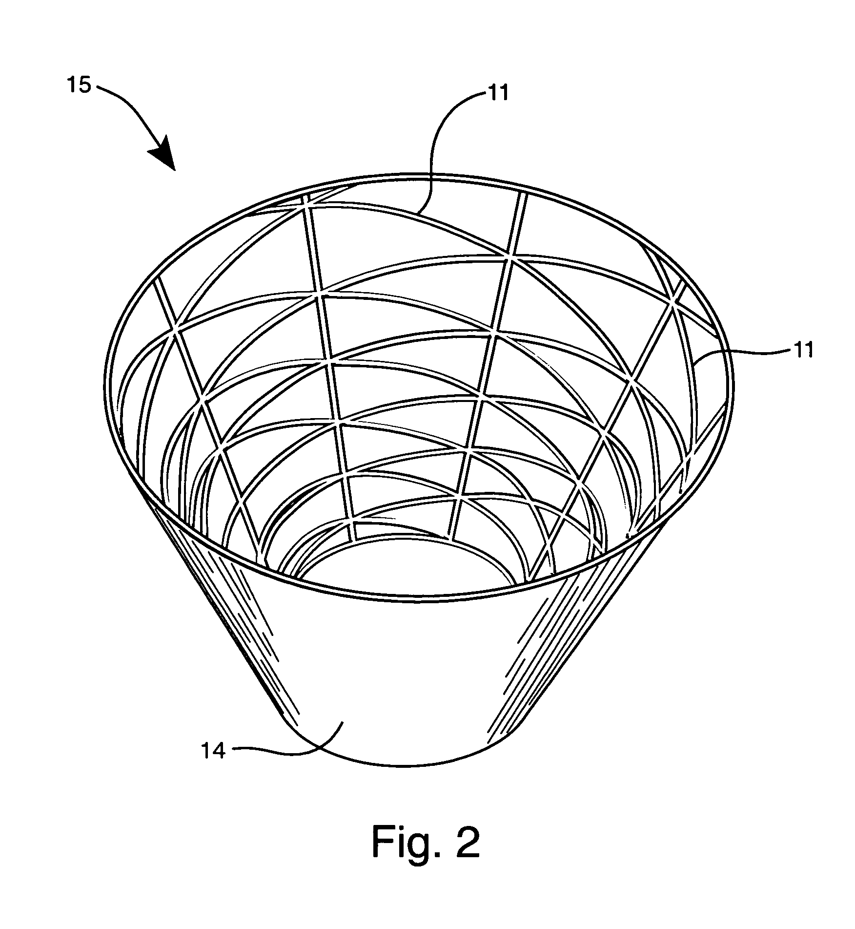
[0019]Hard base tool 10 having the general shape of the desired structure is first fabricated. Base tool 10 has a smooth surface and provides a platform for the ribs to be placed upon. The material selected for base tool 10 must be machinable, thermally stable, and lightweight; for example, particleboard, expansion foam, expansion epoxy, aluminum and graphite.

[0020]Ribs 11 are formed by stacking layers of carbon-fiber tows that have been impregnated with an uncured epoxy matrix material, also known as “tow-preg.” Tow-preg comes in many combinations of fiber and matrix material, and in various sizes such as 12K tow (12,000 fibers per tow), 5K tow (5,000 fibers per tow) and split tape (typically 0.125″ in width and 0.005″ thick). However, many different fibers can be utilized in conjunction with the present invention, such as glass fibers, aramid fibers, or boron fibers. Moreover, these fibers can be combined with a variety of matrix materials, such as polyimides, polyesters, cyanate ...


PUM

PropertyMeasurementUnit
Temperatureaaaaaaaaaa
Forceaaaaaaaaaa
Magnetic fieldaaaaaaaaaa

Abstract

A method for fabricating a grid-stiffened structure from fiber-reinforced composite materials. Ribs are formed on a smooth hard base tool. Expansion blocks are placed in the shallow cavities formed by the ribs and the base tool, and held in place by a synthetic elastomer-based adhesive while a skin is placed over the ribs, expansion blocks, and base tool. The assembly is then placed in a vacuum bag and autoclave cured. After cooling, the expansion blocks are removed and the formed structure is removed from the hard base tool. This abstract is provided to comply with the rules requiring an abstract, and is intended to allow a searcher or other reader to quickly ascertain the subject matter of the technical disclosure. It is submitted with the understanding that it will not be used to interpret or limit the scope or meaning of the claims.

Description

STATEMENT OF GOVERNMENT INTEREST[0001]The invention described herein may be manufactured and used by or for the Government for governmental purposes without the payment of any royalty hereon.BACKGROUND OF THE INVENTION[0002]The present invention is related to the field of fabricating structures having a composite face-sheet reinforced with composite ribs. More specifically, the invention is a method for fabricating such structures by inserting expansion blocks in between the uncured ribs, then removing the blocks after the structure has been cured and removed from a hard base tool.[0003]Rib-stiffened structures are used in a wide variety of applications and configurations. These structures typically consist of a thin skin, or face-sheet, integrally connected to a series of rib or blade stiffeners. The face-sheet can be placed on either the internal or external portion of the structure. The rib-stiffeners typically form repeating patterns that create either rectangular or triangular ...

Claims


Application Information

Patent Timeline
IPC IPC(8): B29D31/00B27N3/10B28B7/22B29C45/14B29C53/58B29C53/80B29C69/00B29C70/86B65H81/00B65C3/26B32B27/00B29D22/00B29D99/00
CPCB29C53/566B29C53/587B29C70/342B29D22/00B29D99/001B29D99/0014B29L2031/3082B32B1/00B32B5/26B32B2260/021B32B2260/046B32B2262/106B32B2307/726B32B2605/18B64C1/068B64C3/187B64C3/22B64C2001/0072Y02T50/40
Inventor WEGNER, PETER M.GANLEY, JEFFREY M.JOHNSON, BRICE A.VAN WEST, BARRY P.
Owner THE UNITED STATES OF AMERICA AS REPRESETNED BY THE SEC OF THE AIR FORCE
Why Eureka
Try Eureka