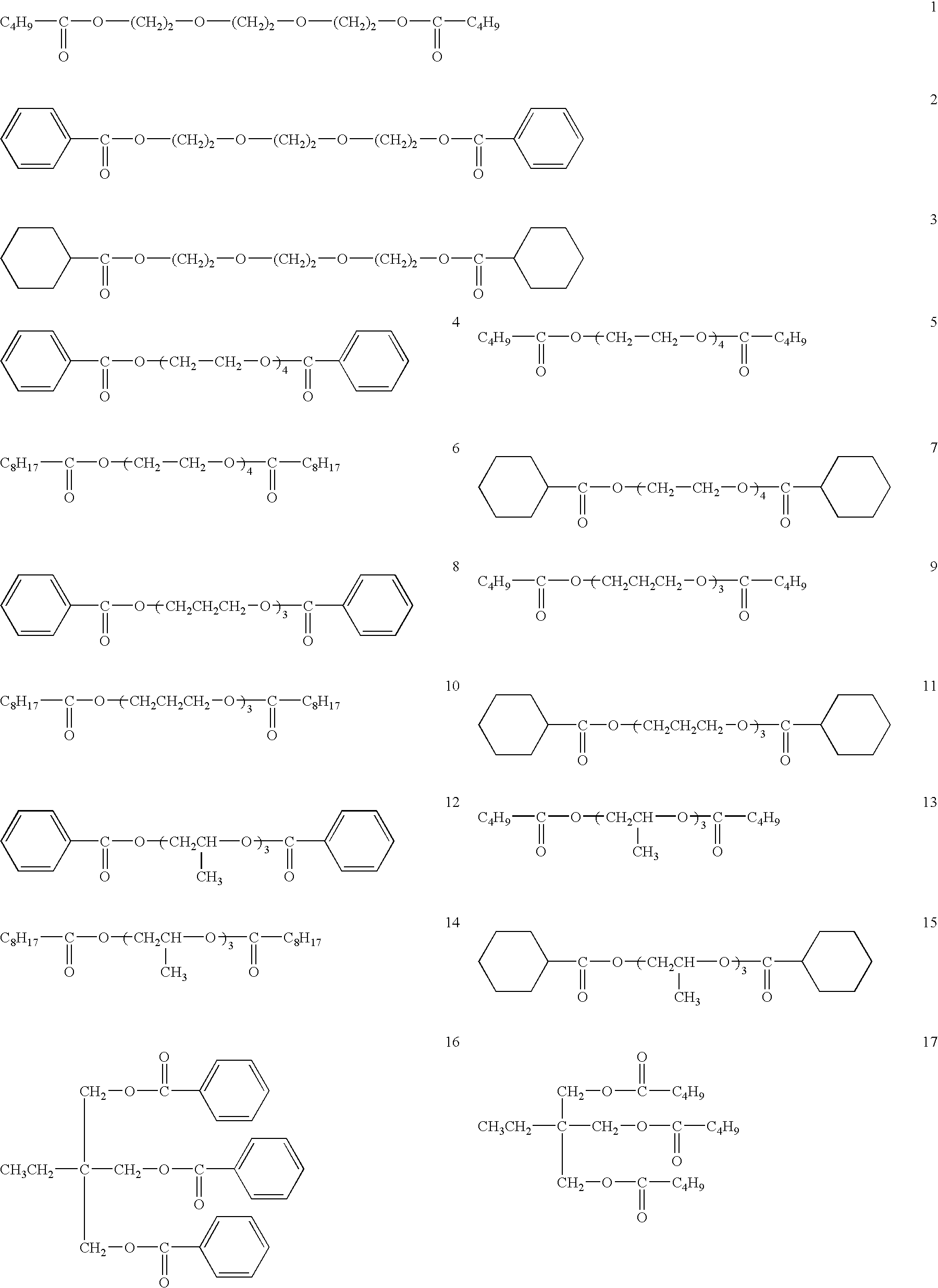
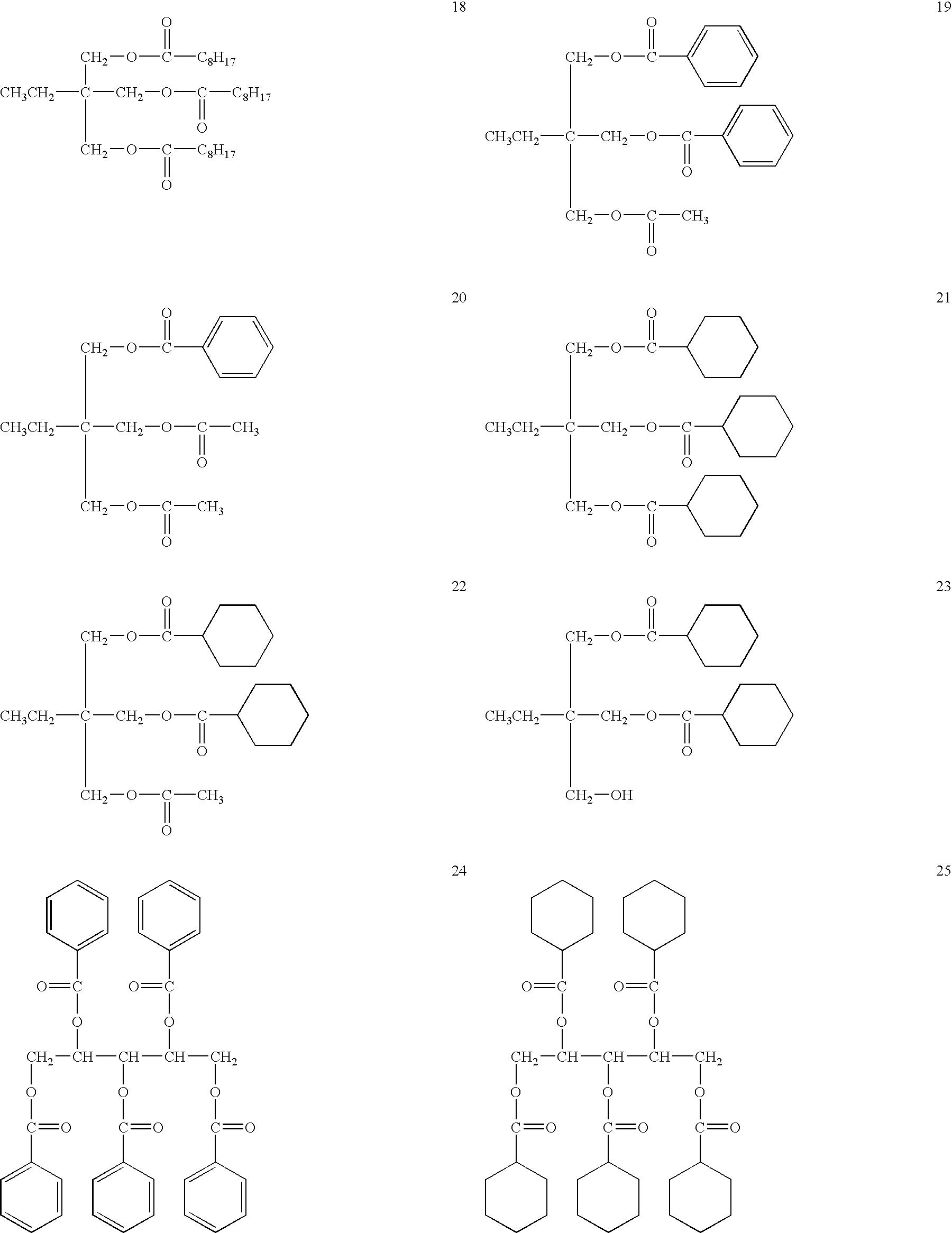
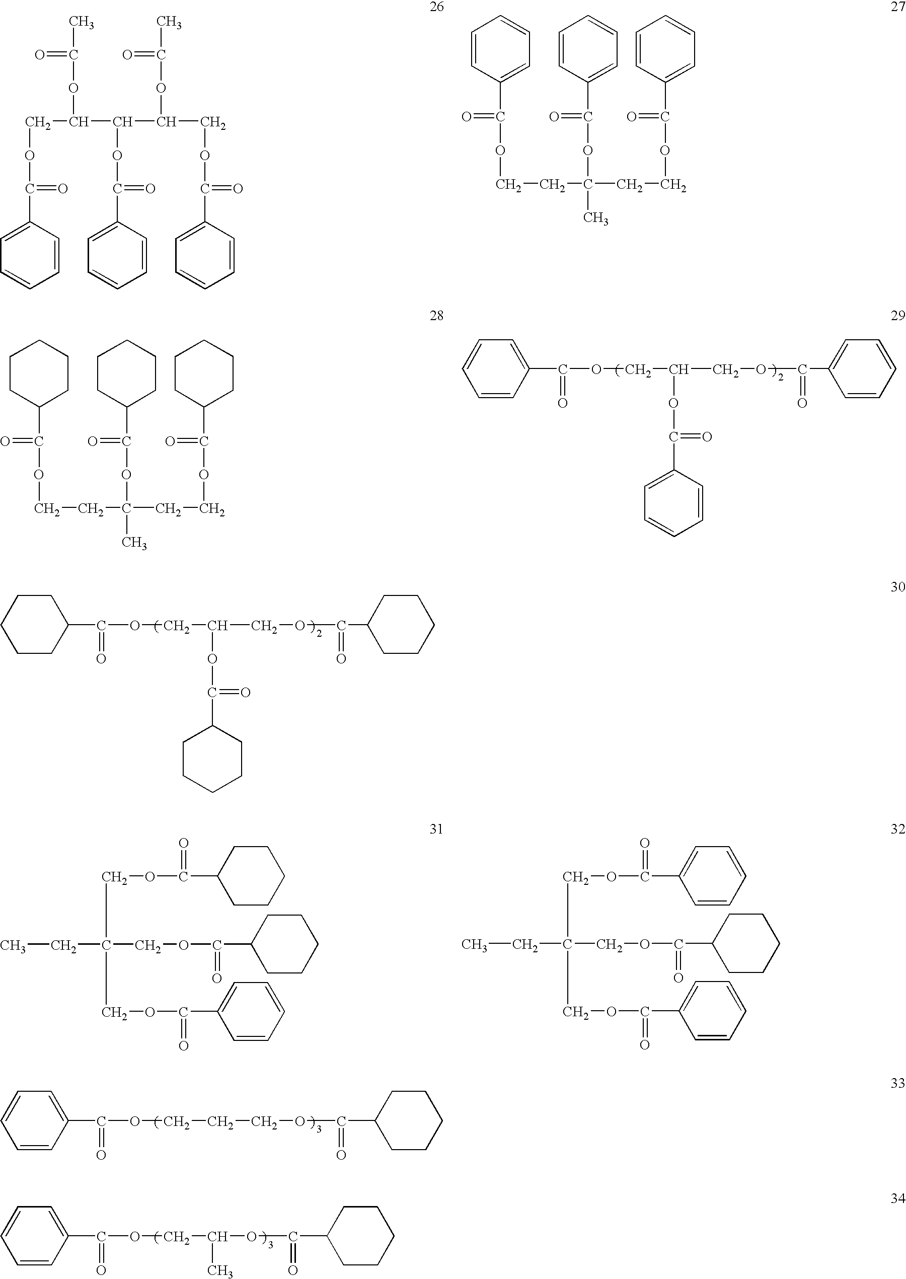
Retardation film, polarizing plate, and liquid crystal display device

a technology of retardation film and polarizing plate, which is applied in the direction of polarizing elements, instruments, transportation and packaging, etc., can solve the problems of low productivity of norbornene film using water-based adhesives, affecting display quality (viewing angle) of liquid crystal display devices, and changing retardation values reversibly, etc., to suppress the fluctuation of retardation values and display qualities. stable

Active Publication Date: 2009-01-20
KONICA MINOLTA OPTO
View PDF8 Cites 16 Cited by
  • Summary
  • Abstract
  • Description
  • Claims
  • Application Information

AI Technical Summary

Benefits of technology

[0010]An object of this invention is to provide retardation films, polarizing plates, and liquid crystal display devices whose display qualities (viewing angle) are more stable by suppressing fluctuations of retardation values which are the faults in the conventional cellulose retardation films.
[0029]This invention can provide retardation films, polarizing plates, and liquid crystal display devices whose display qualities are stable by suppressing fluctuations of retardation values which are the faults in the conventional cellulose retardation films.

Problems solved by technology

However, the retardation value of this film changes reversibly when the humidity changes although the degree of the change is lower than that of the conventional TAC film.
In other words, a problem is that the display quality (viewing angle) of a liquid crystal display device is affected by a retardation change.
To solve this problem, the use of a NORBORNENE film was taken into consideration but the NORBORNENE film using water-based adhesives is low in productivity because it is not dried up quickly.
Further, this problem with retardation changes sometimes occurred also when such retardation films and liquid crystal display devices were kept in hot and humid environments during transportation.
Further, since the display quality (viewing angle) of a liquid crystal display device is determined by a retardation value, even if a change of a retardation is small, if the retardation value is not appropriate, there may be a case that a fluctuation of the display quality (viewing angle) of a liquid crystal display device becomes large.

Method used


Image

  • Retardation film, polarizing plate, and liquid crystal display device
  • Retardation film, polarizing plate, and liquid crystal display device
  • Retardation film, polarizing plate, and liquid crystal display device

Examples


embodiment 1

[0201]First will be explained a method of measuring Ro, Rt, and S.

[0202]The inventors measured average refraction indexes of film components by an Abbe refractometer (4T) and film thicknesses by a commercially available micrometer.

[0203]The inventors kept film samples in a test environment of 23° C. and 55% RH for 24 hours, measured their retardations at a wavelength of 590 nm by an automatic double refractometer KOBRA-21ADH (manufactured by Oji Scientific Instruments), assigned the obtained average refraction index and film thickness values to the following equations, and calculated in-plane retardation (Ro), retardation (Rt) along the thickness of the film sample, and S values. At the same time, the inventors measured the directions of slow axes of the film samples.

Ro=(nx−ny)×d   Equation (i)

Rt=S×d   Equation (ii)

S=((nx+ny) / 2−nz)   Equation (iii)

[0204](where “nx” is a maximum refraction index of the film surface, “ny” is a refraction index in the direction perpendicular to “nx,”“n...

embodiment 2

[0223]The inventors prepared cellulose ester film 201 in the same conditions as cellulose ester film 102 of Embodiment 1 but Embodiment 2 uses the following heat treatment.

[0224]

[0225]The inventors prepared cellulose ester film 201 by taking the steps of stretching a web by the tenter, drying the web by a hot dry air of 105° C. in the conveying and drying process equipped with upper and lower rolls until the quantity of residual solvent is 0.3 mass %, keeping the dried film at 110° C. in an environment (whose atmosphere change rate is 25 times an hour), sandwiching the web by multiple sets of nip rolls to give a pressure of 10 kPa to the web, cooling the web down to the room temperature, and taking up the web by a take-up roll.

[0226]The inventors prepared cellulose ester films 202 and 203 in the same test conditions but the heating temperature, atmosphere change rate, and pressurization are changed as shown in Table 2 and the free volume radius is controlled.

[0227]The atmosphere cha...

embodiment 3

[0239]>

[0240]The inventors prepared an alkaline-saponificated polarizing plate from the above-prepared cellulose ester films as the raw material samples.

[0241]

Saponification process: 2M-NaOH50° C., 90 secondsRinse process: Water30° C., 45 secondsNeutralization process: 10 mass % HCl30° C., 45 secondsRinse process: Water30° C., 45 seconds

[0242]After the saponification, rinse, neutralisation, and rinse processes in that order, the films were dried at 80° C.

[0243]

[0244](Polarizer A: polyvinyl alcohol)

[0245]The inventors prepared a 24 μm-thick polarizer by taking the steps of uniaxial-stretching a polyvinyl alcohol film of 120 μm thick (at a temperature of 110° C. and a stretching magnification of ×5), immersing the drawn film in an aqueous solution of 0.075 g of iodine, 5 g of potassium iodide, and 100 g of water for 60 seconds and then in an aqueous solution of 6 g of potassium iodide, 7.5 g of boric acid, and 100 g of water at 68° C., rinsing and drying thereof.

[0246](Polarizer B: Et...


PUM

PropertyMeasurementUnit
thicknessaaaaaaaaaa
thicknessaaaaaaaaaa
thicknessaaaaaaaaaa

Abstract

A retardation film which contains a cellulose derivative and a plasticizer wherein the thickness of the film is 10 to 50 μm, Ro in Equation (i) is in the range of 30 to 100 nm, Rt in Equation (ii) is in the range of 100 to 300 nm, and S in Equation (iii) is 0.0002 or more but not exceeding 0.030.Ro=(nx−ny)×d  Equation (i)Rt=S×d  Equation (ii)S=((nx+ny) / 2−nz)  Equation (iii)(where “nx” is a maximum refraction index of the film surface, “ny” is a refraction index in the direction perpendicular to “nx,”“nz” is a refraction index along the thickness of the film, and “d” is the thickness of the film.)

Description

[0001]This application is based on Japanese Patent Application No. 2005-198521 filed on Jul. 7, 2005, in Japanese Patent Office, the entire content of which is hereby incorporated by reference.BACKGROUND OF THE INVENTION[0002]This invention relates to a retardation film, a polarizing plate, and a liquid crystal display device.[0003]A liquid crystal display device uses a retardation film to expand its viewing angle. The retardation film is provided between a polarizer and a liquid crystal cell. Namely, the retardation film is placed between a liquid crystal cell and a polarizing plate obtained by laminating the both surfaces of a polarizer produced by stretching an iodine-doped PVA (polyvinyl alcohol) with protective films made of TAC (triacetyl cellulose). There are various ways of placing the retardation film between a polarizer and a liquid crystal cell according to retardation values and characteristics. For example, the polarizing plate can have only one film on one side or two ...

Claims


Application Information

Patent Timeline
Patent Type & Authority Patents(United States)
IPC IPC(8): G02F1/13363
CPCC08J5/18G02B5/3083C08J2301/00Y10T428/105Y10T428/1041Y10T428/1077C09K2323/031C09K2323/035C09K2323/057G02B5/30G02F1/1335G02F1/13363
Inventor TAMAGAWA, MINORIMICHIHATA, ISAMUKUZUHARA, NORIYASU
Owner KONICA MINOLTA OPTO
Why Eureka
Try Eureka