
Energy storage devices

a technology of energy storage and energy storage, which is applied in the direction of electrolytic capacitors, non-aqueous electrolyte cells, electrochemical generators, etc., can solve the problems of limiting the cycle life, fire and explosion, and the tendency of lithium metal electrodes to develop dendrite surfaces

Inactive Publication Date: 2009-01-20
COMMONWEALTH SCI & IND RES ORG +1
View PDF16 Cites 21 Cited by
  • Summary
  • Abstract
  • Description
  • Claims
  • Application Information

AI Technical Summary

Benefits of technology

[0018]It has been demonstrated in the present application that the described room temperature ionic liquid (RTIL) electrolytes provide uniform deposition of lithium metal onto an electrode (i.e. provide uniform lithium deposition morphology), together with good release of lithium back into the electrolyte, resulting in cycling of lithium at high efficiency. In addition the electrolyte is nonvolatile and nonflammable.
[0020]Solid electrolyte interphase-forming additives are shown to improve the deposit morphology and efficiency of the lithium cycling process. The gelling additives provide a gel material while retaining the conductivity of the liquid. This offers specific benefits over liquids in that it will enable fabrication of a flexible, compact, laminated device free from leakage and capable of construction with varying geometry.
[0021]The electrolytes of the present invention are liquid at their intended use temperature, and have characteristics that make them suitable for use in energy storage devices, such as secondary lithium batteries, and particularly lithium metal batteries. The electrolytes have high stability towards lithium, and provide long cycle life with a lithium metal electrode.
[0033]Suitable methods for charging and conditioning the energy storage devices, batteries or cells to improve the cycling rate and cycle life of the devices, batteries or cells have also been identified. The charging method comprises charging, for at least a part of the charging stage (i.e. for at least 5 minutes), at a charge rate of less than 0.25 mAcm−2. The conditioning method comprises the steps of discharging and recharging the device, battery or cell, wherein the recharging is conducted at a rate of less than 0.25 mAcm−2 for at least a part of the recharging stage.

Problems solved by technology

However, when ‘traditional’ solvents are used in combination with lithium metal negative electrodes, there is a tendency for the lithium metal electrode to develop a dendritic surface [1].
The dendritic deposits limit cycle life and present a safety hazard due to their ability to short circuit the cell—potentially resulting in fire and explosion.
These shortcomings have necessitated the use of lithium intercalation materials as negative electrodes (creating the well-known lithium-ion technology), at the cost of additional mass and volume for the battery.
However lithium ion motion in polymer electrolytes is mediated by segmental motions of the polymer chain leading to relatively low conductivity.
The low conductivity and low transport number of the polymer electrolytes has restricted their application in practical devices.
Alternative solvents such as 1,3 dioxolane have been trialled with some success (i.e. uniform lithium deposition morphology) but have been found to react with lithium during cycling of the battery—thus the electrolyte eventually dries out and the battery fails prematurely [2].
Room temperature ionic liquids have been known for a long time, although those studied before 1992 were moisture sensitive, which hampered the development of practical applications.
However, compared to other solvent systems, published research pertaining to the use of room temperature ionic liquids in lithium secondary batteries is sparse.
Few, if any, of the systems proposed have been demonstrated to be capable of use in practice.
Research on other systems indicates that the battery would have insufficient cycling efficiency or would be subject to severe limits on the possible charging / discharging rates.
Moreover, little work if any has been reported to show whether the proposed systems enable lithium to be both taken up by the negative electrode, and importantly then released.

Method used


Image

  • Energy storage devices
  • Energy storage devices
  • Energy storage devices

Examples


example 1

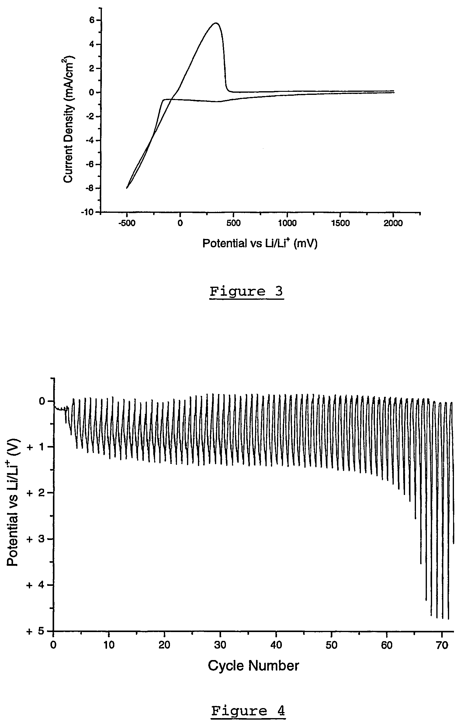
[0167]The electrochemical stability of a 0.5 mol / kg lithium bis(trifluoromethanesulfonyl)amide in methyl butyl pyrrolidinium bis (trifluoromethanesulfonyl)amide on a lithium electrode deposited on to a Ni substrate is determined by cyclic voltammetry using the 3-electrode cell described above (with Ni working electrode). The test was conducted at 100 mVs−1 and at ambient temperature. The results of the test are illustrated in FIG. 3. High reversibility is observed, with no indication of degradation of the electrolyte.

example 2

[0168]To show the ability of the electrolyte to reversibly cycle lithium a cycling efficiency experiment was conducted. A solution of 0.5 mol / kg lithium bis(trifluoromethanesulfonyl)amide in methyl butyl pyrrolidinium bis (trifluoromethanesulfonyl)amide was made up and a cycling efficiency experiment carried out at 0.25 mAcm−2 and 1 Ccm−2 (0.25 Ccm−2 cycled fraction) on a Pt electrode at 50° C. The electrode cycles for 63 cycles (FIG. 4), indicating a cycling efficiency of 94.0%.

example 3

[0169]The test of example 2 is repeated on a platinum substrate at the higher rate of 1.0 mAcm−2 and 1 Ccm−2 (0.25 Ccm−2 cycled fraction). The electrode cycles for 430 cycles (FIG. 5), indicating a cycling efficiency of 99.1%. Because of the large number of cycles, only the maximum deposition (reduction) and dissolution (oxidation) potentials for each cycle are shown.


PUM

PropertyMeasurementUnit
boiling pointaaaaaaaaaa
temperatureaaaaaaaaaa
melting pointsaaaaaaaaaa

Abstract

Pyrrolidinium-based room temperature ionic liquids, and phosphorus and arsenic analogues, are used as electrolytes in energy storage devices including secondary lithium batteries, supercapacitors and asymmetric battery-supercapacitors. The electrolytes preferably contain lithium ions as the charge-carrying species. The electrolytes are in a liquid state at the operating temperature.

Description

[0001]This invention relates to the application of pyrrolidinium based room temperature ionic liquids as electrolytes in energy storage devices such as secondary lithium batteries. The present invention further relates to energy storage devices, and particularly secondary lithium batteries, containing the electrolyte.BACKGROUND TO THE INVENTION[0002]Lithium rechargeable batteries (i.e. secondary lithium batteries, in which lithium ions are the principal charge carriers) are important devices in the field of energy storage. They offer advantages over other secondary battery technologies due to their higher gravimetric and volumetric capacities as well as higher specific energy.[0003]Secondary lithium batteries fall into two classes—those in which the negative electrode is lithium metal, known as a “lithium metal battery”, and those in which the negative electrode is comprised of a lithium intercalation material, known as “lithium-ion batteries”. In terms of specific energy and power,...

Claims


Application Information

Patent Timeline
Patent Type & Authority Patents(United States)
IPC IPC(8): H01M10/40H01G9/035H01G9/038H01G9/155H01M10/052H01M10/0563H01M10/0565H01M10/26H01M10/36
CPCH01G9/038H01G9/155H01G11/56H01G11/58H01G11/62H01M10/052H01M10/0563H01M10/0565H01M10/0567H01M12/005H01M2300/0022H01M2300/0085Y02E60/122Y02E60/13H01M10/0568H01M2300/0045Y02E60/10
Inventor HOLLENKAMP, ANTHONY FRANKHOWLETT, PATRICK CRAIGMACFARLANE, DOUGLAS ROBERTFORSYTH, STEWART ALEXANDERFORSYTH, MARIA
Owner COMMONWEALTH SCI & IND RES ORG
Learn More