Self-cleaning socket for microelectronic devices

a microelectronic device and socket technology, applied in the direction of coupling contact members, coupling device connections, instruments, etc., can solve the problems of unreliable contact between the contactor tip and the mating solder ball, economic loss, and tip fouling, etc., to achieve the effect of increasing manufacturing ease and extreme miniaturization

Active Publication Date: 2009-02-17
CENTIPEDE SYST
View PDF26 Cites 70 Cited by
  • Summary
  • Abstract
  • Description
  • Claims
  • Application Information

AI Technical Summary

Benefits of technology

[0014]An advantage of the present invention is provided by the debris capturing action from repeated mating of the contactor with terminals of devices under test. Debris falling into the tube of the contactor is captured within the axial cavity of the tube. In one or more embodiments of the invention, thin laser-cut slots through the tube are too narrow to allow debris of significant size to escape out through the side walls of the tube. The volume inside a tube is selected to be sufficient to hold debris for the lifetime of the contactor, obviating the need for cleaning to remove a buildup of deb...

Problems solved by technology

Remnants of the surface film, including solder flux, solder oxide, organic contamination, and surface films build up contamination on the crown tip, fouling of the tip and causing unreliable contact between the contactor tip and a mating solder ball.
Fouling of crown tip contactors is responsible for economic loss due to tester down time during cleaning as well as due to false rejects resulting from contact failure.
Socket cleaning and contactor failure due to contamination fouling are significant caused of tester down time in a semiconductor test facility.
Miniaturization and density of the mechanically stamped and formed springs are limited by present capabilities to a certain minimum size.
Sockets with contactors so made are limited in density by the complexity of stamping and forming very small miniaturized springs.
Because of small compliance in a vertical direction, a miniature stamped and formed spring may be unable to accommodate motion of a contactor support relative to a ball mated to it, thereby allowing vibration, mechanical shock load and forces, flexure, and the like to cause the contactor to slide over the surface of the ball and potentially lose contact.
It has also been observed that repeated microscopic...

Method used


Image

  • Self-cleaning socket for microelectronic devices
  • Self-cleaning socket for microelectronic devices
  • Self-cleaning socket for microelectronic devices

Examples


Embodiment Construction

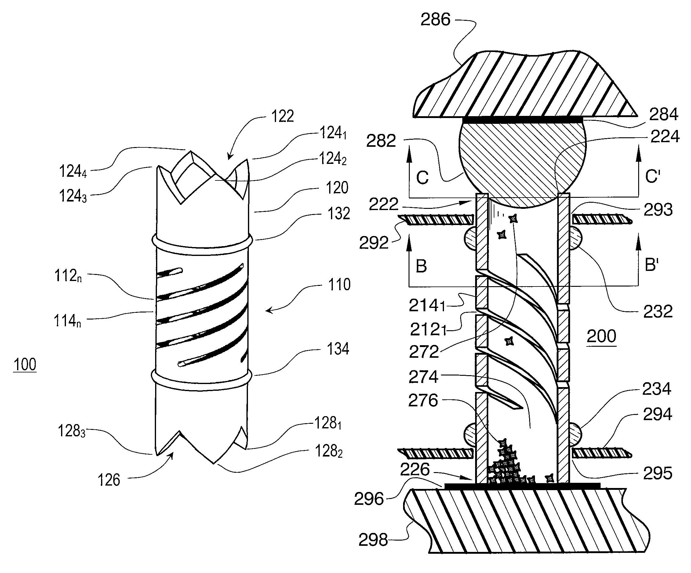
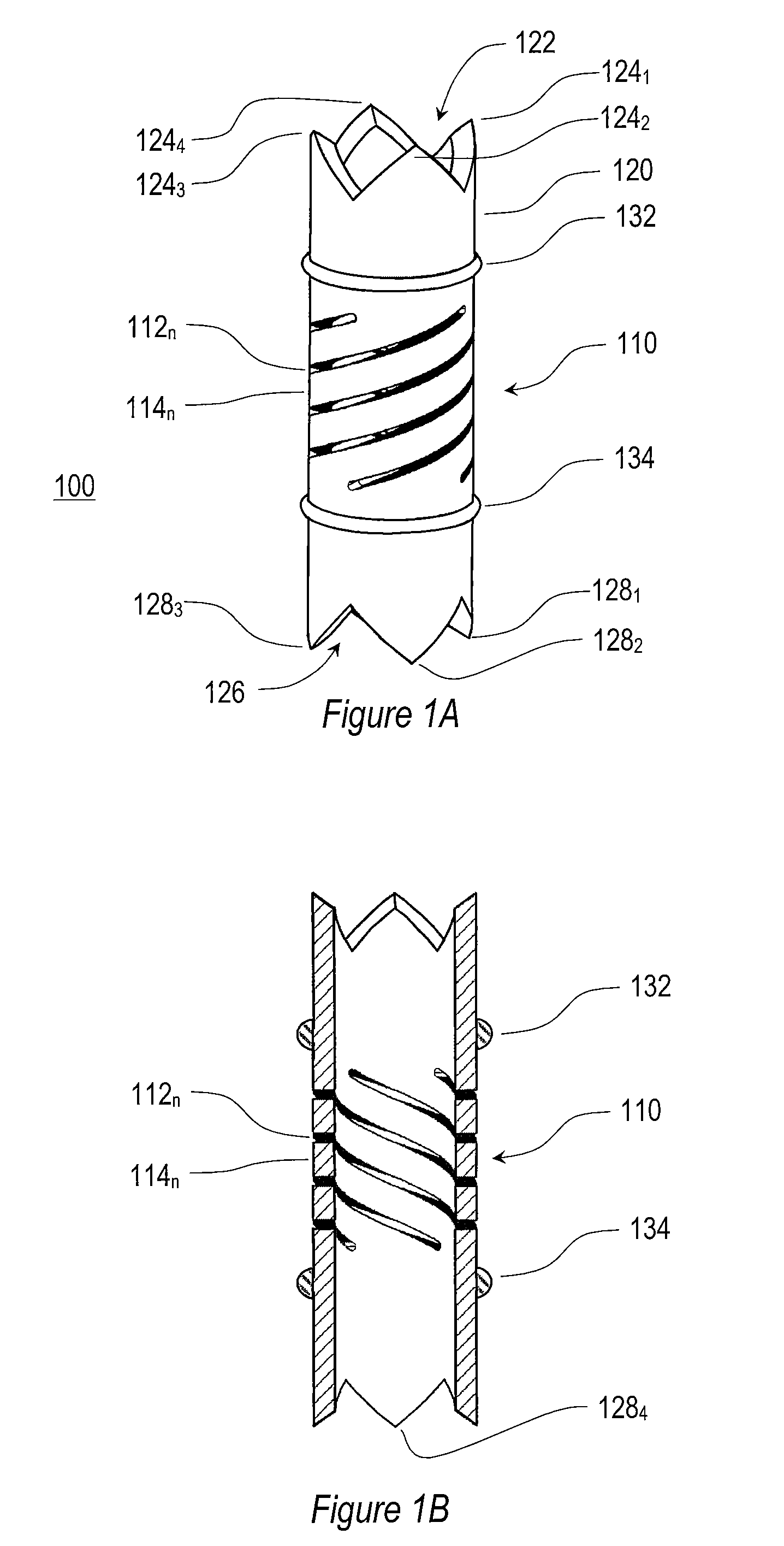
[0027]As illustrated by an embodiment shown in FIGS. 1A and 1B, contactor 100 comprises a hollow cylindrical electrically conductive metal tube which is cut through by a series of helical slots 112n in a midsection 110 to form resilient helical legs 114n that terminate in a collar 120 at the frontal end of contactor 100. In this embodiment, there are four equally-spaced legs 114n (FIG. 1A). (Labels are omitted from all but one of the legs 114n and slots 112n for clarity of exposition.) Two or more legs 114n are needed to support collar 120 horizontally and to prevent tipping of the collar when a terminal (not shown) is urged against collar 120. Legs 114n are held in place by the cylindrical collar region 120 in the uncut end portion, herein called the collar 120 of contactor 100. Annular flanges or retaining rings 132 and 134 may be provided around the circumference of contactor 100 to facilitate mounting of the contactor in a socket assembly employing for example retaining sheets (...


PUM


Abstract

A self-cleaning socket for contacting terminals on a microelectronic device wherein the first end of compliant tubular contactors rotate and wipe against terminals urged downwardly against the first end of the contactors. A rotational wipe of a contactor against a mating terminal breaks through any surface contamination layers on the terminal, thereby producing good electrical contact therebetween. Rotation of the first end of a contactor is caused by a downward deflection of a collar supported by two or more helical legs along a midsection of the contactor. Deflection of the collar distorts the resilient helical legs, each of which exerts a force on the collar which add up to produce a torsional force on the collar, thereby providing a rotational wipe in response to a downward urging of a terminal against the contactor. A void along the axis of the tubular contactor provides a reservoir to hold debris dislodged from the terminal and to keep the debris from interfering with operation of the contactor.

Description

BACKGROUND OF THE INVENTION[0001]This invention relates to sockets used for microelectronic devices. More particularly, this invention relates to self cleaning contactors used in sockets for testing microelectronic devices with ball terminals or with flat terminals. One or more embodiments of the present invention relate to a self-cleaning electrical contactor for making electrical connections to high performance microelectronic devices, for example, and without limitation, integrated circuits (“ICs”), including microprocessors, chips for peripheral functions and RAM memories.[0002]Sockets are used widely in electronics to burn-in and test microelectronic devices. Sockets are routinely used in systems for: (a) testing electronic device performance (an assortment of socket types have been developed to connect to a device under test (“DUT”) having a wide variety of terminals and configurations), or (b) burn-in of electronic devices at elevated temperatures. A socket for burn-in or tes...

Claims


Application Information

Patent Timeline
IPC IPC(8): H01R12/00
CPCG01R1/0491G01R1/06722G01R1/07314H01R13/111H01R13/2407G01R3/00
Inventor DI STEFANO, THOMAS H.FARACI, ANTHONY B.KARAVAKIS, KONSTANTINEDI STEFANO, PETER T.
Owner CENTIPEDE SYST
Why Eureka
Try Eureka