Spin injection magnetization reversal element

a technology of reversal element and spin injection, which is applied in the field of basic structure elements, can solve the problems of inability to retain magnetization, minute magnetization is unstable, and the resistance of recorded magnetization to thermal agitation is degraded, so as to reduce the critical current density necessary, improve the efficiency of electron spin injection, and ensure thermal stability

Inactive Publication Date: 2009-03-10
FUJI ELECTRIC CO LTD
View PDF7 Cites 4 Cited by
  • Summary
  • Abstract
  • Description
  • Claims
  • Application Information

AI Technical Summary

Benefits of technology

[0012]The present invention is based on the finding that, in making a ferromagnetic fixed layer and a ferromagnetic free layer opposite to each other with an isolation layer in between, spin-polarized electrons can be efficiently injected or reflected between the ferromagnetic fixed layer and the ferromagnetic free layer by increasing the opposed areas or by making the ferromagnetic fixed layer substantially surround the ferromagnetic free layer.
[0019]In a related GMR structure element, the main purpose for improving the efficiency of electron spin injection has been to intensify s-d interaction in a ferromagnetic fixed layer in order to realize approximately 100% spin polarization. In the present invention, however, by adopting a new arrangement of a ferromagnetic fixed layer and a ferromagnetic free layer, efficient injection or reflection of polarized electron spins becomes possible between the ferromagnetic fixed layer and the ferromagnetic free layer without relying on s-d interaction. As a result, it becomes possible to reduce the critical current density necessary for magnetization reversal, or it becomes possible to ensure thermal stability by increasing the volume or the saturation magnetization of the ferromagnetic free layer.

Problems solved by technology

However, making the volume and the magnitude of saturation magnetization of a ferromagnetic free layer small results in degradation of resistance of recorded magnetization to thermal agitation, and this makes minute magnetization unstable.
As a result, a problem arises which makes retention of magnetization impossible.

Method used


Image

  • Spin injection magnetization reversal element
  • Spin injection magnetization reversal element
  • Spin injection magnetization reversal element

Examples


example 1

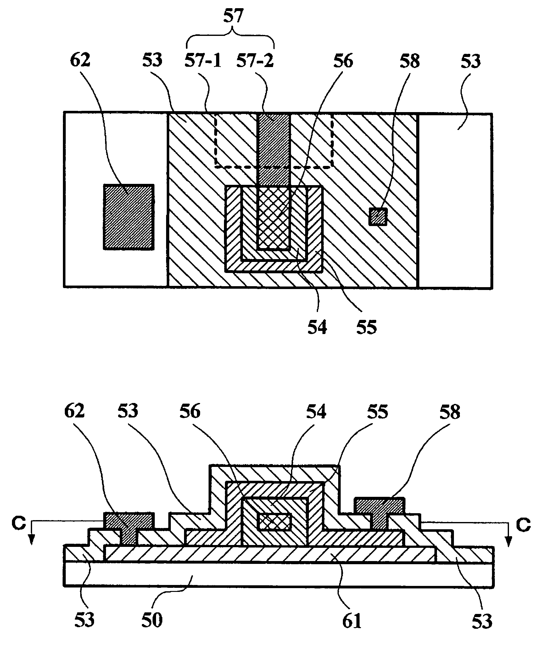
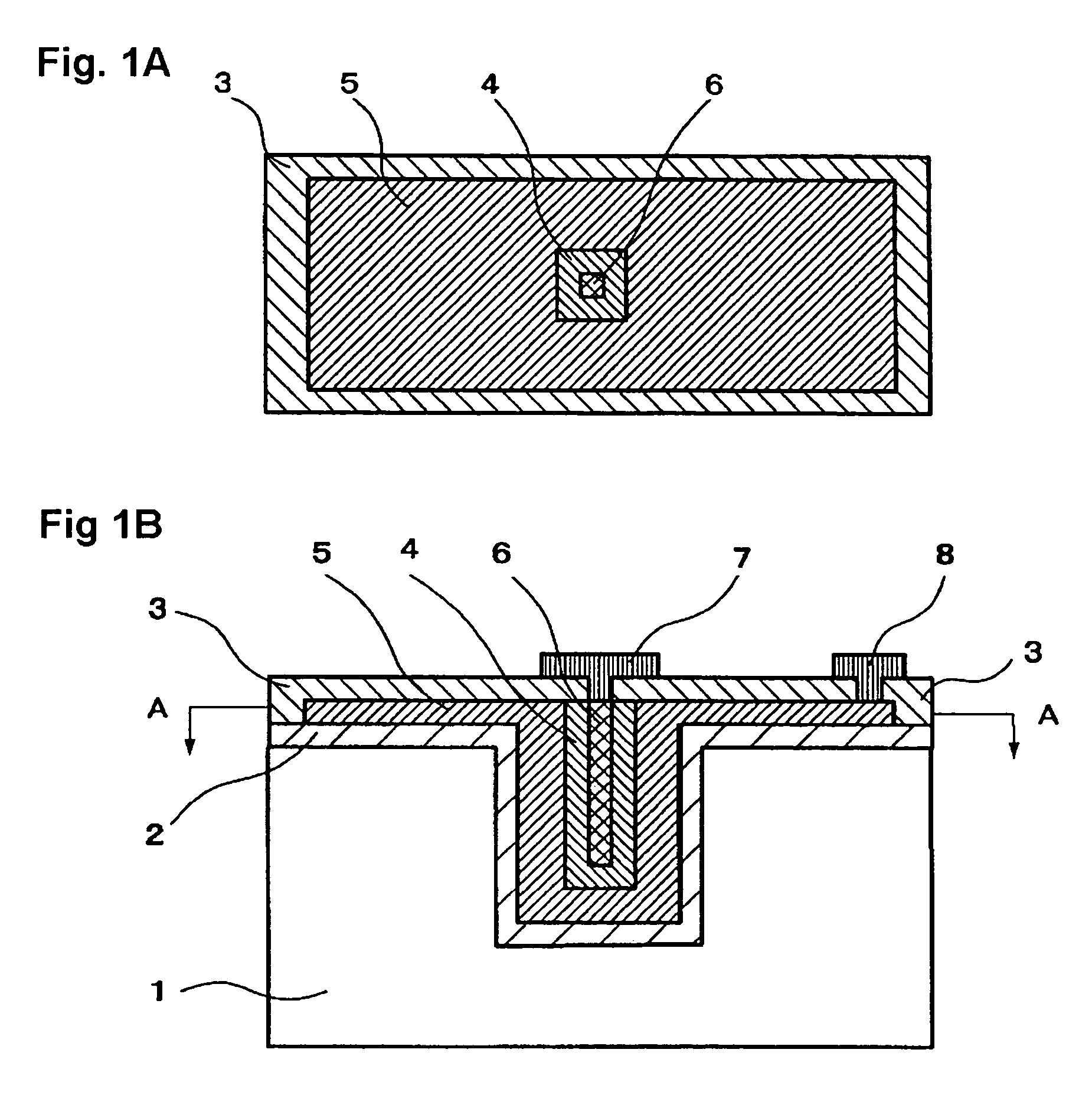
[0054]FIGS. 1A and 1B are views for explaining the arrangement of an element as Example 1 according to the invention, with FIG. 1B being a schematic cross sectional view and FIG. 1A being a schematic cross sectional view taken on line A-A of FIG. 1B. Substrate insulation layer 2 is formed on the surface of substrate 1 formed with a trench structure having a square horizontal cross section. Ferromagnetic fixed layer 5 is arranged on substrate insulation layer 2 while filling the trench structure so as to surround a square-prism-like ferromagnetic free layer 6 with isolation layer 4 in between. Insulation layer 3 is provided over ferromagnetic fixed layer 5, isolation layer 4 and ferromagnetic free layer 6. Ferromagnetic fixed layer 5 is connected to an external power supply (not shown) through fixed layer electrode 8 by way of a through hole opened in insulation layer 3. Ferromagnetic free layer 6 is connected to the external power supply through free layer electrode 7 provided throu...

example 2

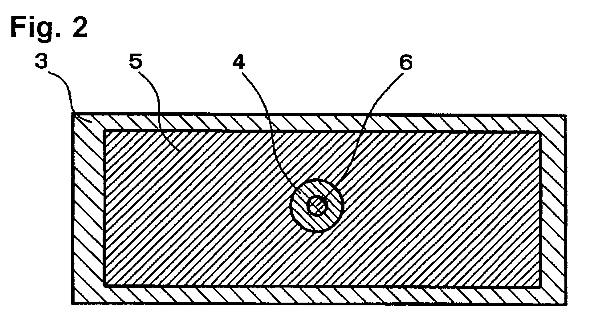
[0059]FIG. 2 is a schematic cross sectional view for explaining the arrangement of an element of Example 2 according to the invention equivalent to the element shown in FIG. 1A. As shown in FIG. 2, the element was fabricated similarly to the element of Example 1, except that a trench structure was formed in a cylinder shape and was provided as Example 2. The shape of ferromagnetic free layer 6 was like a cylinder with a diameter of 10 nm and a depth of 10 nm.

[0060]The operating conditions and characteristics of Example 2 are shown in Table 1. As a result of measuring the resistance values of the element with a detecting current of 300 μA, the resistance value in the high resistance state was 4.6 Ω and that in the low resistance state was 4.0 Ω.

example 3

[0061]Example 3 is an example in which a laminated electrode was additionally provided for ferromagnetic fixed layer 5 in the element of Example 1 to adjust a resistance value. In each of FIGS. 3A and 3B, there is shown the arrangement of Example 3. FIG. 3B is a schematic cross sectional view for explaining the arrangement of Example 3 and FIG. 3A is a schematic cross sectional view taken on line B-B of FIG. 3B.

[0062]After substrate insulation layer 2 with a silicon oxide film has been formed, the element was fabricated similarly to the element as Example 1 to be obtained as Example 3 except that laminated electrode 9 made of Cu was formed with a thickness of 20 nm and the film thickness of the subsequently formed ferromagnetic fixed layer 5 was made 80 nm.

[0063]The operating conditions and characteristics of Example 3 are shown in Table 1. As a result of measuring the resistance values of the element with a detecting current of 300 μA, the resistance value in the high resistance st...


PUM


Abstract

A spin injection magnetization reversal element includes a ferromagnetic fixed layer, an isolation layer and a ferromagnetic free layer. The area of contact between the ferromagnetic fixed layer and the isolation layer is larger than an area of contact between the ferromagnetic free layer and the isolation layer. The ferromagnetic fixed layer may be divided into ferromagnetic first fixed layer and ferromagnetic second fixed layer, and the isolation layer may be divided into first isolation layer and second isolation layer. The ferromagnetic first fixed layer may be arranged on one of opposed principal surfaces of the ferromagnetic free layer with the first isolation layer in between, and the ferromagnetic second fixed layer may be arranged on the other of the opposed principal surfaces of the ferromagnetic free layer with the second isolation layer in between. The element holds recorded magnetization and can reverse magnetization with a small current density.

Description

CROSS REFERENCE TO RELATED APPLICATIONS[0001]This application claims priority from application Serial No. JP 2005-185876, filed on Jun. 27, 2005, the contents of which are incorporated herein in their entirety.BACKGROUND OF THE INVENTION[0002]A. Field of the Invention[0003]The present invention relates to a basic structure element forming a magnetic sensor or a magnetic memory, and a device using the element. More specifically, the invention relates to an element that controls electron spin injection to form a magnetic random access memory having a large capacity and including no mechanical driving section, or to an element forming a weak electric current sensor that detects electron spin injection, and a device using the element.[0004]B. Description of the Related Art[0005]FIG. 8 is a view schematically showing a cross sectional structure for explaining an example of an arrangement of a previously proposed GMR (Giant Magneto-Resistance) element making use of a GMR effect. For examp...

Claims


Application Information

Patent Timeline
Patent Type & Authority Patents(United States)
IPC IPC(8): H01L29/82
CPCG11C11/16H01L43/08H10N50/10
Inventor SAITO, AKIRA
Owner FUJI ELECTRIC CO LTD
Why Eureka
Try Eureka