
Structured self-cleaning surfaces and method of forming same

a self-cleaning surface and structure technology, applied in the field of structured self-cleaning surfaces, can solve the problems of sacrificing self-cleaning capability, sacrificing the durability of polymeric surfaces, and not revealing a surface optimized for micro-roughness, so as to improve durability, improve durability, and improve durability.

Inactive Publication Date: 2009-04-28
FERRO CORP
View PDF25 Cites 41 Cited by
  • Summary
  • Abstract
  • Description
  • Claims
  • Application Information

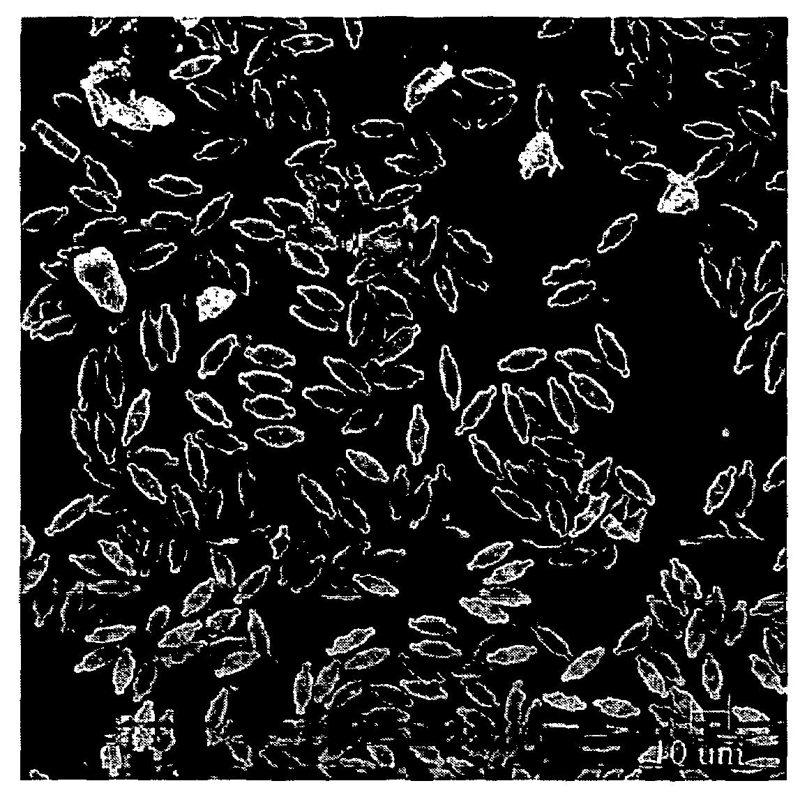
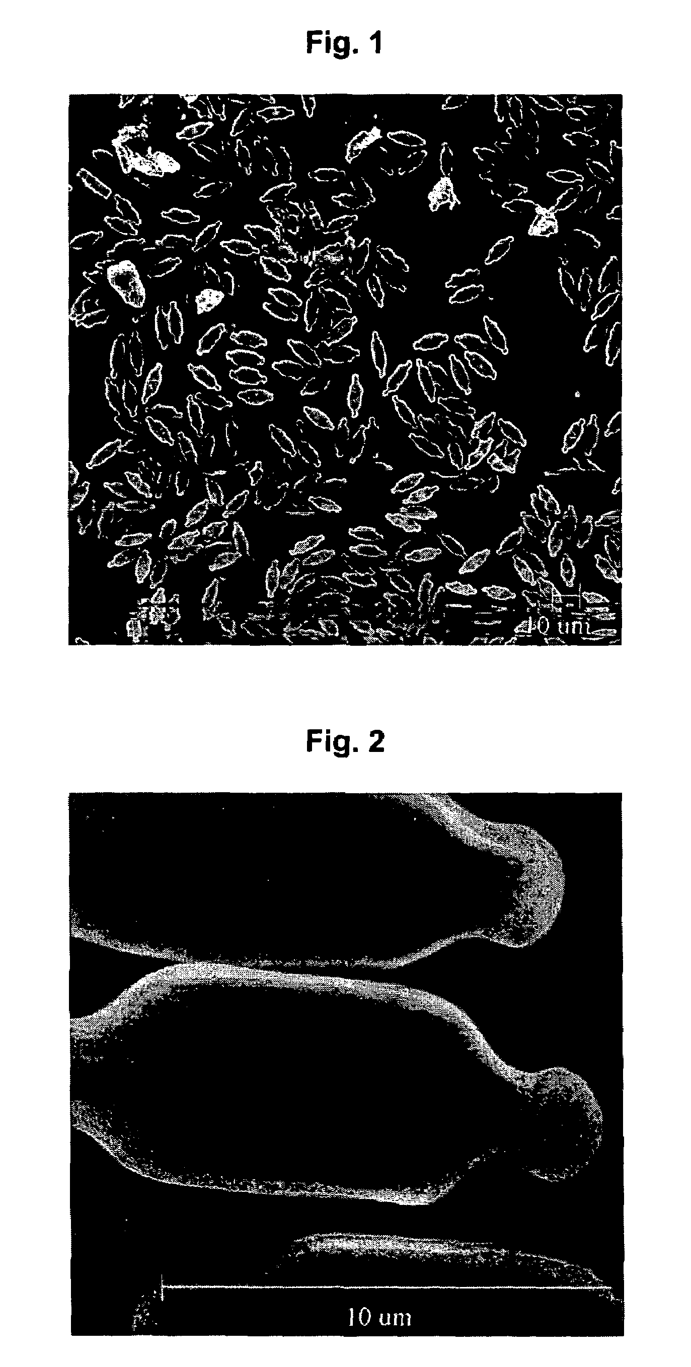
AI Technical Summary

Benefits of technology

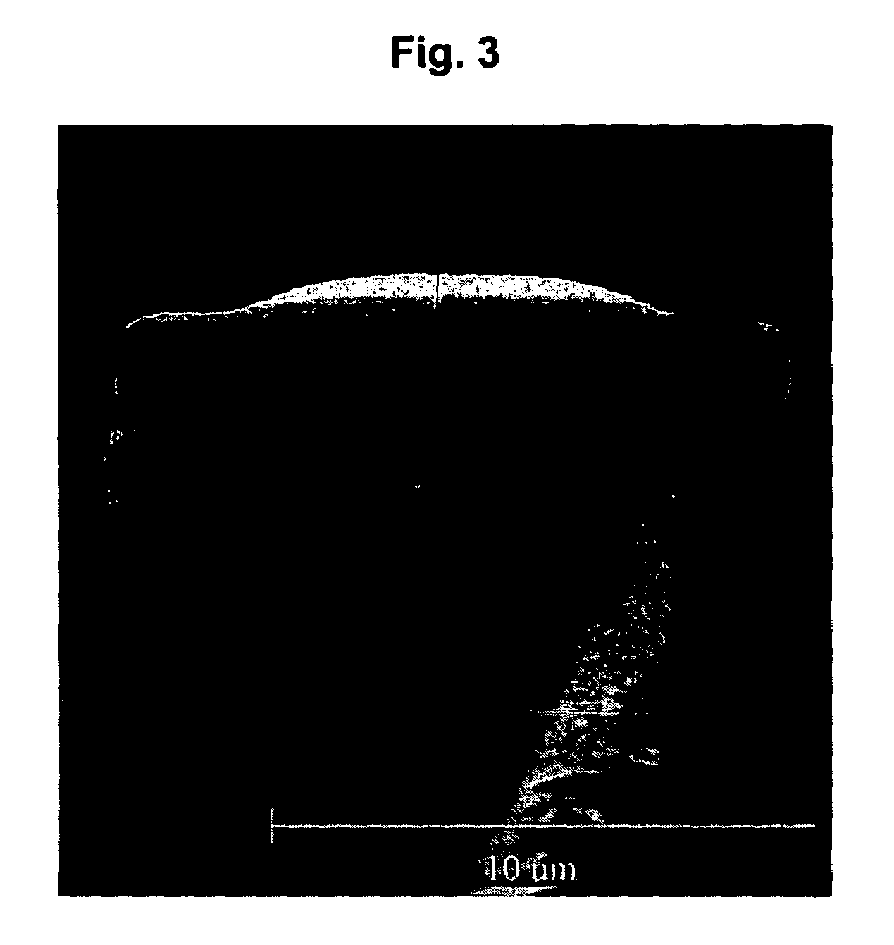
[0008]U.S. Published Pat. Appl. No. 2003 / 0096083 teaches that surfaces of objects, such as containers for receiving liquid, can be modified by grit blasting or acid etching to achieve the micro-roughness necessary for self-cleaning capability. It also teaches the use of a “contour-following coating” applied to the underlying micro-rough surface. The invention is a relatively simple and flexible two-step, low temperature process capable of operating on various substrate surface geometries. One disadvantage of the invention, however, is that it may be constrained to substrate materials with sufficient toughness (metal or polymeric materials) to withstand the aggressive grit blasting step. Other substrates, such as glass or ceramic materials, may be prone to micro-cracking from the grit blasting procedure, making them susceptible to fracture or reduced transparency. Roughness on the nanometer scale is also not claimed by this method, which may limit the degree of self-cleaning capability obtained.
[0009]U.S. Pat. Appl. No. 2003 / 0152780 teaches the creation of a micro-rough surface comprised of glass flux and structure-forming particles in the 0.1 to 50 μm range. Good durability of the micro-rough surface is achieved in certain embodiments of the invention in which the glass flux layer is sintered at high temperature to glass or ceramic substrate materials. Self-cleaning capability is obtained with the addition of a thin, hydrophobic coating. In one embodiment, reactive alkyl or preferably fluoroalkyl silanes and oligomeric alkyl or fluoroalkyl siloxanes are cured over the glass flux layer, providing a hydrophobic coating a few nanometers thick. Rather than relying on adhesion, this cured layer has improved durability because it is chemically bonded (Si—O—Si bridge) to the glass flux-coated substrate. In practice, this invention may suffer from less than optimal durability and micro-roughness as the hydrophobic layer is relatively thin and the structure-forming particles exceed 0.1 μm in size.
[0010]Although progress has been made in the development of self-cleaning industrial surfaces and coatings, inventive processes producing an optimal combination of high durability, self-cleaning capability, flexibility and cost efficiency remain elusive. Self-cleaning coatings are often used on automobile windshields for improved poor weather visibility. But the methods currently employed are limited in durability and require frequent application of the self-cleaning coating product. Similarly, the costs of cleaning industrial building windows, particularly those in multi-story buildings, and the windows of cruise ships could be dramatically reduced if a self-cleaning substrate surface were available with high abrasion resistance. Thus, the need for a highly structured, durable, nano-rough surface remains important.
[0011]Diatoms are a large group of single-celled algae species that possess a highly ornate, porous and intricate skeleton (frustule), comprised of silica, alumina and other substances. The structure of the frustules varies significantly between various diatom species. The typical size of frustules ranges from 0.75 to 1,000 μm with nanoscale-sized features. The frustules are very durable when one considers their size, and are often found intact after thousands of years in the millions of tons of diatomaceous earth sediments found on the ocean floor.
[0012]With such diversity in microscopic features, porosity and durability, it should be no surprise that a significant body of prior art has taught the use of diatoms for use in filtration applications. Many particle separation methods rely on diatomite products in the processing of beer, for example. Diatomite is also used as filler in paints and paper. U.S. Published Pat. Appl. No. 2001 / 0023233 teaches the purification of diatomaceous earth to produce a highly pure, silica particulate. The resulting product can be used in various filtration applications and retains the structural features of the diatom frustules.BRIEF SUMMARY OF THE INVENTION
[0013]The present invention involves growing diatoms on a surface for the purpose of forming nanoscale-sized siliceous structures on the surface. In accordance with the invention, diatom films are grown on various substrates, which are then fired to remove all organic material from the diatoms and produce a surface coated with intricate, nanoscale-sized structures. The nanoscale-sized structured surface is subsequently treated with a hydrophobic film-forming agent to form a structured self-cleaning surface.

Problems solved by technology

Like the previous self-cleaning inventions described, these polymeric surfaces are also likely to have low durability.
Substantial effort has been made to improve the durability of self-cleaning surfaces, but most involve costly, complicated methods that ultimately sacrifice self-cleaning capability.
However, one drawback of this method is that it does not disclose a surface optimized for the micro-roughness necessary for the self-cleaning effect.
One disadvantage of the invention, however, is that it may be constrained to substrate materials with sufficient toughness (metal or polymeric materials) to withstand the aggressive grit blasting step.
Other substrates, such as glass or ceramic materials, may be prone to micro-cracking from the grit blasting procedure, making them susceptible to fracture or reduced transparency.
Roughness on the nanometer scale is also not claimed by this method, which may limit the degree of self-cleaning capability obtained.
In practice, this invention may suffer from less than optimal durability and micro-roughness as the hydrophobic layer is relatively thin and the structure-forming particles exceed 0.1 μm in size.
Although progress has been made in the development of self-cleaning industrial surfaces and coatings, inventive processes producing an optimal combination of high durability, self-cleaning capability, flexibility and cost efficiency remain elusive.
But the methods currently employed are limited in durability and require frequent application of the self-cleaning coating product.

Method used


Image

  • Structured self-cleaning surfaces and method of forming same
  • Structured self-cleaning surfaces and method of forming same
  • Structured self-cleaning surfaces and method of forming same

Examples


example 1

[0041]One part by volume of concentrated hydrochloric acid was dissolved in 3600 parts of distilled water. This solution was labeled Acid 1. One part by volume of concentrated hydrochloric acid was dissolved in 200 parts of distilled water. This solution was labeled Acid 2. 106.36 g of denatured ethanol was placed in a round bottom flask. 0.7 g of tetraethylorthosilicate (TEOS) was weighed and added drop wise to the stirring ethanol. The beaker was rinsed with 10 g of ethanol. 1.4 g of Acid 1 was weighed. The acid was added drop wise to the stirring solution. 10 g of ethanol was used to rinse the beaker. This ethanol was added to the round bottom flask. While continuing to stir the solution, a condenser was placed on the round bottom flask and heat was applied from a heating mantle. The heat was increased incrementally to achieve a temperature of 60° C. After heating at 60° C. for one hour, the heating mantle was removed from the round bottom flask and the flask was bathed in cool t...

example 2

[0042]An epoxy-lined 1-liter ceramic mill jar was charged with a 50% by volume load of 0.7 mm zirconia beads. Then, the following ingredients were added in order, with swirling of the mill jar between additions to disperse each new component: 383.6 g of denatured ethanol, 8 g of distilled water, 0.4 g of concentrated hydrochloric acid, 4 g of TEOS and 4 g of Aerosil 200 (fumed silica with a surface area of 200 m2 / g, available from Degussa). The mill was then placed in an agitator and the agitator was run for 20 minutes to disperse the Aerosil into the solution. The resulting suspension was filtered from the mill media into a jar. The suspension was labeled as Lotus Nano-Structuring Spray.

example 3

[0043]106.36 g of denatured ethanol was placed in a round bottom flask. 1.71 g of Dynasylan F8261 (1,1,2,2-tetrahydroperfluorooctyltriethoxysilane, available from Degussa) was weighed and added drop wise to the stirring ethanol. The beaker was rinsed with 10 g of ethanol. 1.4 g of Acid 1 from Example 1 was weighed. The acid was added drop wise to the stirring solution. 10 g of ethanol was used to rinse the beaker. This ethanol was added to the round bottom flask. While continuing to stir the solution, a condenser was placed on the round bottom flask and heat was applied from a heating mantle. The heat was increased incrementally to achieve a temperature of 60° C. After heating at 60° C. for one hour, the heating mantle was removed from the round bottom flask and the flask was bathed in cool tap water to return the solution to approximately room temperature (20° C.). 1.4 g of Acid 2 from Example 1 was then weighed. This acid solution was added drop wise to the stirring ethanol / TEOS s...


PUM

PropertyMeasurementUnit
diameteraaaaaaaaaa
heightaaaaaaaaaa
heightaaaaaaaaaa

Abstract

The present invention involves growing diatoms on a surface for the purpose of forming nanoscale-sized siliceous structures on the surface. In accordance with the invention, diatom films are grown on various substrates, which are then fired to remove all organic material from the diatoms and produce a surface coated with intricate, nanoscale-sized structures. The nanoscale-sized structured surface is subsequently treated with a hydrophobic film-forming agent to form a structured self-cleaning surface.

Description

BACKGROUND OF THE INVENTION[0001]1. Field of Invention[0002]The present invention relates to structured self-cleaning surfaces and a method of forming the same. More particularly, the method of the present invention involves growing diatoms on a surface to form siliceous nanoscale-sized structures and treating the structures with a hydrophobic agent to form the structured self-cleaning surface.[0003]2. Description of Related Art[0004]In order to possess a true “self-cleaning” capability, a surface must have both hydrophobic properties and a micro-rough surface structure. Nature produces such an effect in the leaves of the lotus plant. A waxy, hydrophobic substance and pyramidal elevations with spacing on the order of a few micrometers characterize the surface of the lotus leaf. When water droplets come into contact with the lotus leaf, adhesion is minimal because the leaf surface is hydrophobic and high contact angles are formed. Further, the micro-rough texture reduces the contact ...

Claims


Application Information

Patent Timeline
Patent Type & Authority Patents(United States)
IPC IPC(8): B05D3/02
CPCC03C17/22C03C17/34C04B41/009C04B41/5024C04B41/52C04B41/85C04B41/89C03C17/25C04B41/4535C04B41/4554C04B41/4582C04B41/5022C04B41/4933C04B33/00Y10T428/259C03C2217/213C03C2217/76C03C2217/77C03C2218/111C04B2103/0001C04B2111/2069
Inventor AXTELL, III, ENOS A.SAKOSKE, GEORGE E.SWILER, DANIEL R.HENSEL, MICHAELBAUMANN, MARTINMATALKA, DAVID J.NUCCETELLI, GARY L.
Owner FERRO CORP
Learn More