
Semiconductor device with flowable insulation layer formed on capacitor and method for fabricating the same

a flowable, capacitor technology, applied in semiconductor devices, semiconductor/solid-state device details, capacitors, etc., can solve the problems of generating plasma damage on the bottom layer consisting of capacitors, and the inability to perform a low-temperature process with bpsg, etc., to achieve good planarization characteristics

Active Publication Date: 2009-05-26
SK HYNIX INC
View PDF18 Cites 2 Cited by
  • Summary
  • Abstract
  • Description
  • Claims
  • Application Information

AI Technical Summary

Benefits of technology

The present invention provides a semiconductor device with a flowable insulation layer formed on a capacitor by performing a low-temperature process along with a good planarization characteristic but without degrading characteristics of bottom layers comprising the capacitor. The invention also provides a method for fabricating the semiconductor device. The technical effect of the invention is to improve the insulation of the capacitor without compromising the performance of the underlying substrate layers.

Problems solved by technology

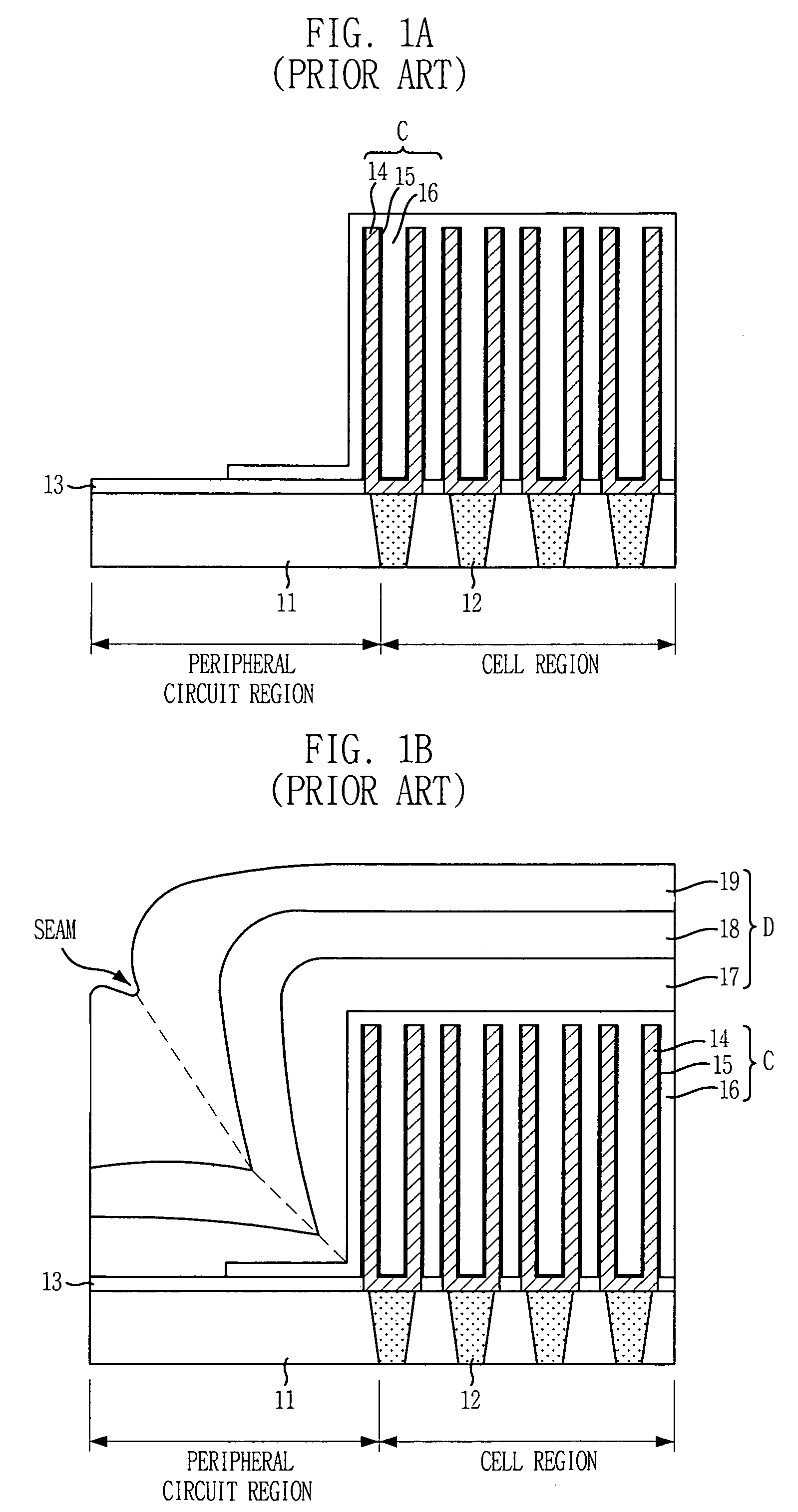
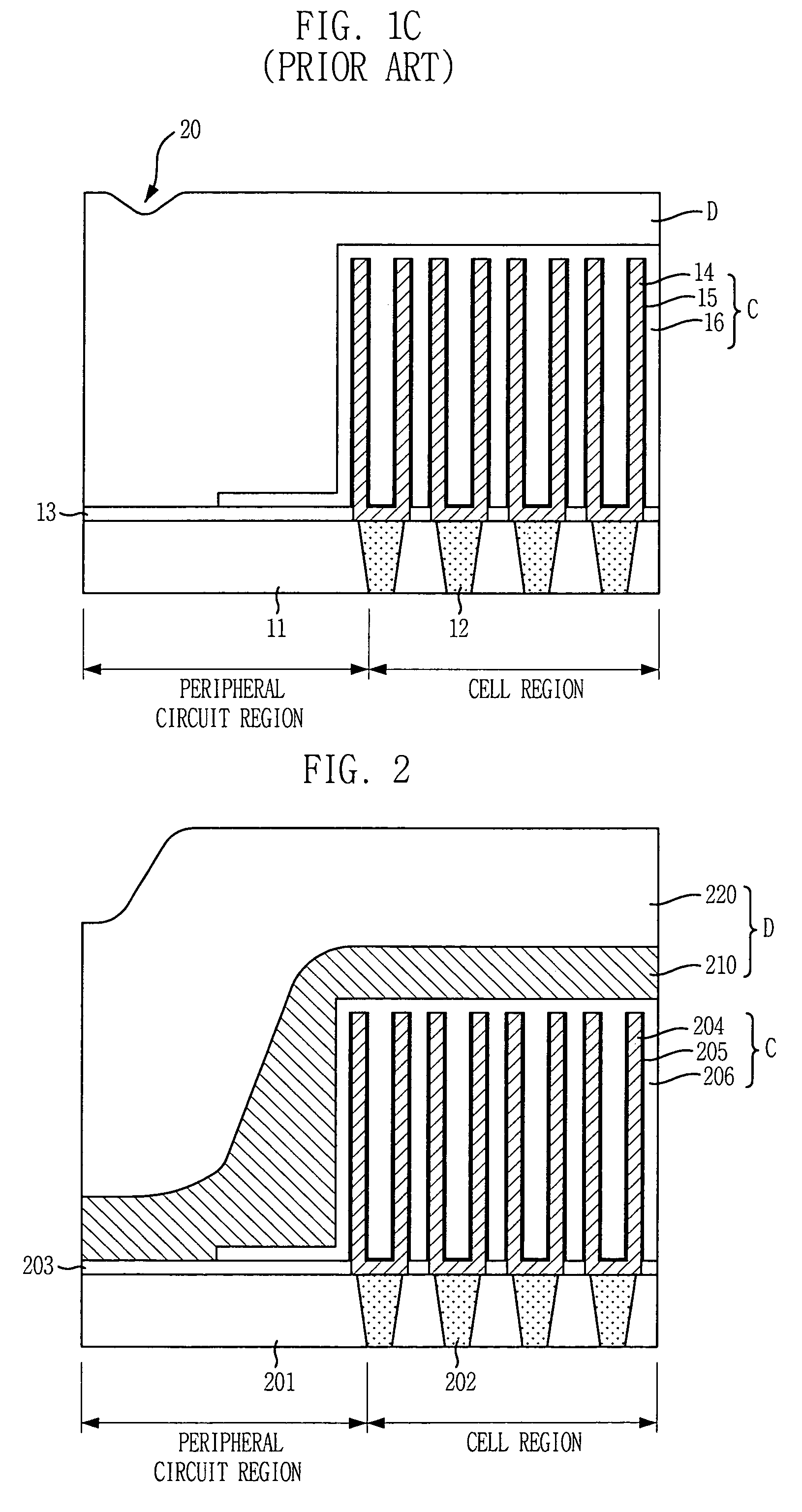
Especially in this drawing, a problem related to the conventional method for forming the insulation layer on the capacitor is depicted.
Meanwhile, to remove the cavity 20 of the insulation layer D, a high density plasma-chemical vapor deposition (HDP-CVD) method having excellent planarization and step-coverage characteristics can be used to form the insulation layer D. However, the deposition mechanism of the HDP-CVD method is a repeating steps of etching and depositing, and thus, there is a disadvantage of generating plasma damage on bottom layers consisting the capacitor.
In case of using a borophosphosilicate glass (BPSG) capable of reflowing because the BPSG is doped with boron (B) and phosphorus (p) as the insulation layer D, it is essential to employ a high-temperature thermal process for reflowing the BPSG at a temperature of 800° C. Therefore, using BPSG is not appropriate to perform a low-temperature process.

Method used


Image

  • Semiconductor device with flowable insulation layer formed on capacitor and method for fabricating the same
  • Semiconductor device with flowable insulation layer formed on capacitor and method for fabricating the same
  • Semiconductor device with flowable insulation layer formed on capacitor and method for fabricating the same

Examples


first embodiment

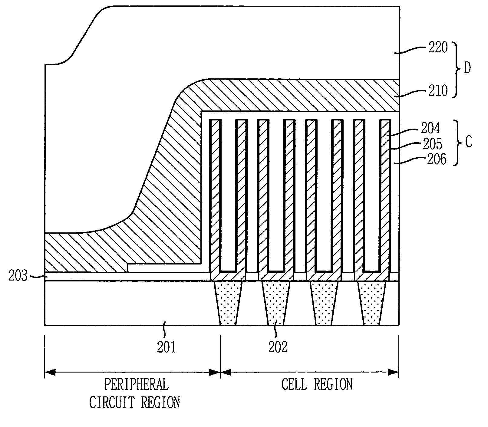
[0026]First, FIG. 2 shows one exemplary substrate structure in accordance with the present invention.

[0027]As shown, a plurality of capacitors C are formed on a substrate provided with a first insulation layer 201, contact plugs 202 and an etch stop layer 203. Each of the capacitors C includes a lower electrode 204 being contacted to the contact plug 202 and having a cylinder shape, a dielectric layer 205 covering the lower electrode 204 and an upper electrode 206 formed on the dielectric layer 205. The capacitors C are formed in a typical DRAM cell region and are not formed in a peripheral region. Hence, there exists a height difference of at least approximately 10,000 Å in a boundary between the cell region and the peripheral region.

[0028]Subsequently, a flowable insulation layer 210 that does not generate a seam in region where a height difference is high by having flowability during the deposition of the flowable insulation layer 210 is formed on the capacitor C.

[0029]Especially...

second embodiment

[0036]FIG. 3 is a cross-sectional view showing another exemplary substrate structure, wherein an insulation layer is formed on a capacitor in accordance with the present invention.

[0037]Referring to FIG. 3, a plurality of capacitors C are formed on a substrate provided with a first insulation layer 301, contact plugs 302 and an etch stop layer 303. Each of the capacitors C includes a lower electrode 304 being contacted to the corresponding contact plug 302 and having a cylinder shape, a dielectric layer 305 covering the lower electrode 304 and an upper electrode 306 formed on the dielectric layer 305. The capacitor C is formed in a typical DRAM cell region and is not formed on a peripheral region, thereby exhibiting a height difference of at least 10,000 Å in a boundary between the cell region and the peripheral region.

[0038]Subsequently, the USG-based insulation layer 310 formed by a PECVD method is formed on the capacitors C. At this time, a deposited thickness of the USG-based in...

third embodiment

[0043]FIG. 4 is a cross-sectional view of a substrate structure, wherein an insulation layer is formed on a capacitor in accordance with the present invention.

[0044]Referring to FIG. 4, a plurality of capacitors C are formed on a substrate provided with a first insulation layer 401, contact plugs 402 and an etch stop layer 403. Each of the capacitors C includes a lower electrode 404 being contacted to the corresponding contact plug 402 and having a cylinder shape, a dielectric layer405 covering the lower electrode 404 and an upper electrode 406 formed on the dielectric layer 405. The capacitor C is formed in a typical DRAM cell region and is not formed in a peripheral region, thereby exhibiting a height difference of at least 10,000 Å in a boundary between the cell region and the peripheral region.

[0045]Subsequently, USG-based insulation layer 410 is formed on the substrate provided with the plurality of capacitors C with use of a PECVD method. At this time, the USG-based insulation...


PUM


Abstract

Disclosed is a semiconductor device with a flowable insulation layer formed on a capacitor and a method for fabricating the same. Particularly, the semiconductor device includes: a capacitor formed on a predetermined portion of a substrate; an insulation layer formed by stacking a flowable insulation layer and an undoped silicate glass layer on a resulting substrate structure including the substrate and the capacitor; and a metal interconnection line formed on the insulation layer. The method includes the steps of: forming a capacitor on a predetermined portion of a substrate; forming an insulation layer by stacking a flowable insulation layer and an undoped silicate glass layer on a resulting substrate structure including the substrate and the capacitor; and forming a metal interconnection line on the insulation layer.

Description

FIELD OF THE INVENTION[0001]The present invention relates to a semiconductor device; and more particularly, to a semiconductor device with an insulation layer on a capacitor and a method for fabricating the same.DESCRIPTION OF RELATED ARTS[0002]As is known well, a trend in micronization and large scale of integration of a semiconductor memory device is highly demanded to secure enough capacitance of a capacitor included in a dynamic random access memory (DRAM) cell. In order to obtain enough capacitance, a dielectric material is formed by stacking aluminum oxide (Al2O3) and hafnium oxide (HfO2), or an upper electrode and a lower electrode of a capacitor are formed by using a metal such as titanium nitride (TiN).[0003]Accordingly, in case of forming an insulation layer on top of the capacitor, the insulation layer should be formed essentially through a low-temperature process to prevent degradation of bottom layers of the capacitor for instance oxidization of a metal, degradation of ...

Claims


Application Information

Patent Timeline
Patent Type & Authority Patents(United States)
IPC IPC(8): H01L21/8242H10B12/00H01L21/02H01L23/532
CPCH01L21/02134H01L21/02137H01L21/02164H01L21/022H01L21/02211H01L21/02271H01L21/02282H01L21/31633H01L27/10894H01L21/02274H01L28/91H01L21/3124H01L23/53295H01L27/10814H01L2924/0002H10B12/315H10B12/09H01L2924/00H10B12/00
Inventor AHN, SANG-TAESHEEN, DONG-SUNSONG, SEOK-PYOSHIN, JONG-HAN
Owner SK HYNIX INC
Learn More