
Harmonic oscillator using transmission line resonator

a transmission line resonator and harmonic resonator technology, applied in oscillator, semiconductor device details, semiconductor devices, etc., can solve the problems of complex design of harmonic resonators, insufficient suppression, and large amplification levels of wave fsub>, 3fsub>0/sub>, etc., to achieve high quality, easy positioning of connection position of output lines, and high quality.

Inactive Publication Date: 2009-05-26
NIHON DEMPA KOGYO CO LTD +1
View PDF4 Cites 3 Cited by
  • Summary
  • Abstract
  • Description
  • Claims
  • Application Information

AI Technical Summary

Benefits of technology

The present invention provides a harmonic oscillator that suppresses the output of unwanted harmonics, particularly the fourth harmonic, to obtain high-quality output of the desired harmonic. This is achieved by using a transmission line resonator with a specific voltage displacement distribution that minimizes the generation of second harmonic and other higher-order harmonics. The invention also includes a suppression means for the second harmonic, which is a higher-order harmonic with larger amplification levels. The invention also provides a simple and effective configuration for a fourth harmonic oscillator that suppresses the output of second harmonic and other higher-order harmonics.

Problems solved by technology

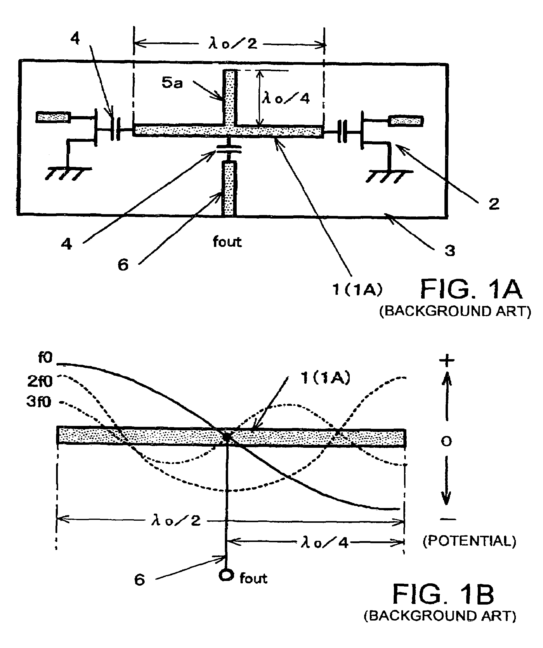
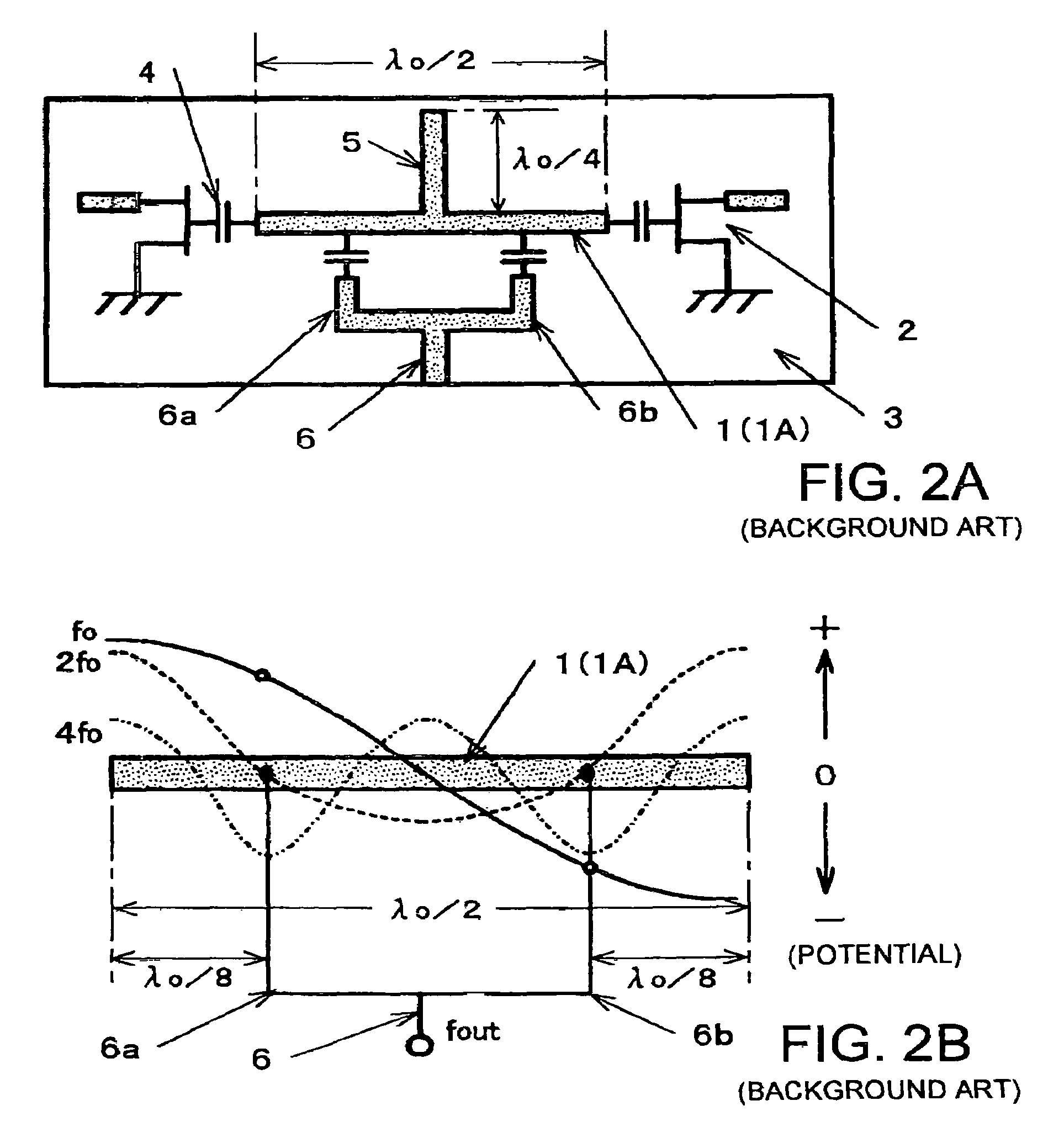
However, in the case of the fourth harmonic oscillator, because output lines 6 are connected at two points at a distance λ0 / 8 from either ends of microstrip line resonator 1A, there is a problem that fundamental wave f0, second harmonic 2f0, and third harmonic 3f0, which have larger amplification levels than that of fourth harmonic 4f0, can not be sufficiently suppressed due to mainly imbalance in the circuit configuration, for example.
Therefore, impedance matching with active elements 2 is difficult, which results in complicated design of the harmonic resonator.

Method used


Image

  • Harmonic oscillator using transmission line resonator
  • Harmonic oscillator using transmission line resonator
  • Harmonic oscillator using transmission line resonator

Examples


first embodiment

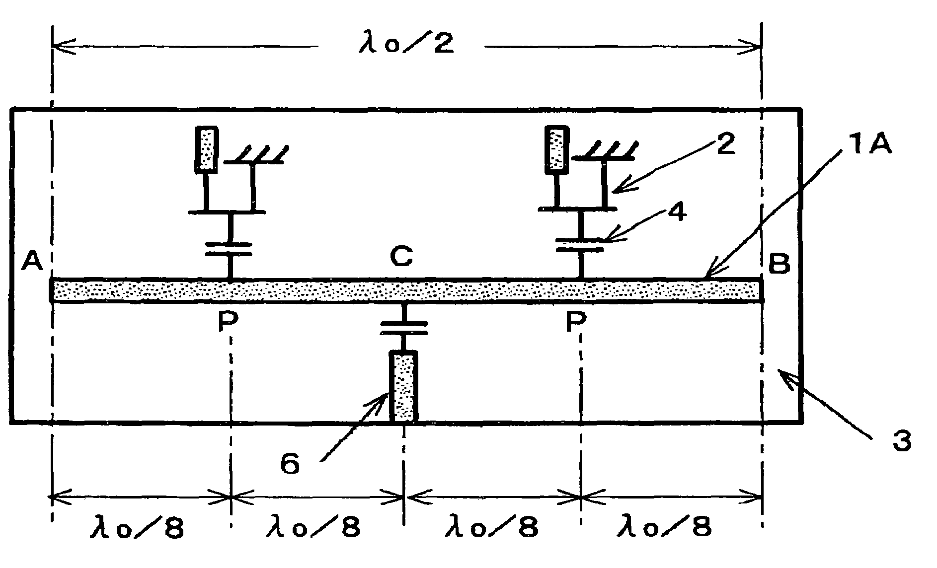
[0048]A fourth harmonic oscillator of a first embodiment of the present invention shown in FIGS. 3A and 3B is configured by providing linear microstrip line resonator 1A as a transmission line resonator 1 on substrate 3 made of a dielectric and the oscillator generates signal having a frequency four times as high as that of fundamental frequency (fundamental wave) f0 of oscillation by resonance in the resonator. The signal line of microstrip line resonator 1A is provided on one main surface of substrate 3, and ground conductor 10 is provided over almost entire surface of the other main surface of substrate 3. In this fourth harmonic oscillator, as described above, linear microstrip line resonator 1A has a length of λ0 / 2 where λ0 is a wavelength corresponding to fundamental wave f0, and two active elements 2 oscillating in opposite phase to each other are connected to resonator 1A through capacitors 4 for loose coupling. In addition, output line 6 for taking out oscillation output is...

second embodiment

[0063]Next, a second embodiment of the present invention will be described. In a fourth harmonic oscillator according to the second embodiment of the present invention shown in FIG. 7, as in the conventional fourth harmonic oscillator shown in FIG. 1, active elements 2 for oscillation are connected at both ends A, B of microstrip line resonator 1A and output line 6 is connected at midpoint C. In order to physically suppress generation of second harmonic in resonator 1A, slot line stabs 5b are provided at positions at a distance λ0 / 8 from either ends of microstrip line resonator 1A toward the center where λ0 is a wavelength corresponding to fundamental wave f0, i.e. positions which are minimum voltage displacement portions for second harmonic.

[0064]Slot line stabs 5b are configured by providing slot-like opening parts in a ground conductor on the back side of substrate 3 made of a dielectric and longitudinal directions of the opening parts are orthogonal to the direction in which mic...

third embodiment

[0071]Next, a third embodiment of the present invention will be described. Although a transmission line resonator provided in a linear form is used in the above described first and second embodiments, the shape of the transmission line resonator is not limited to the linear form, but may be annular, for example. FIG. 9A shows a fourth harmonic oscillator which corresponding to the oscillator shown in FIGS. 3A and 3B but uses annular microstrip line resonator 1C instead of the linear microstrip line resonator.

[0072]Microstrip line ring resonator 1C is provided on the surface of substrate 3 in an annular form in which its circumferential length is λ0 where λ0 is a wavelength corresponding to fundamental wave f0. Therefore, half circumferential length in ring resonator 1C is λ0 / 2. At position C1 which is the bottom end of the circle in FIG. 9A, microstrip line stab 5a which has a length of λ0 / 4 and acts as an electrical short-circuit end for fundamental wave f0 is connected to ring res...


PUM


Abstract

A harmonic oscillator comprises a transmission line resonator in which an oscillation frequency depends on an electrical length of a transmission line and both ends of the transmission line are electrical open ends; an active element for oscillation as a negative resistance connecting to the transmission line resonator; an output line connected to a midpoint portion of the transmission line resonator; and electrical and / or physical suppressing means for suppressing a voltage displacement distribution of second harmonic among the even-order harmonics. The suppressing means is provided at a position which is at least a minimum voltage displacement portion for the second harmonic between the midpoint portion and either ends of the transmission line resonator.

Description

BACKGROUND OF THE INVENTION[0001]1. Field of the Invention[0002]The present invention relates to a harmonic oscillator for high frequency in, for example, microwave or millimeter-wave band, using a transmission line resonator, and more particularly a harmonic oscillator suitable for obtaining fourth harmonic having a frequency four times as high as that of a fundamental wave or second harmonic having a frequency two times as high as that of the fundamental wave, among harmonics related to the fundamental wave of an oscillation frequency.[0003]2. Description of the Related Arts[0004]A high-frequency oscillator is employed in an optical communication system or its peripheral equipment, for example, and high performance and low cost are required. As such a high-frequency oscillator, the present inventors have already proposed a harmonic oscillator using a transmission line resonator in each of US 2003 / 0090332 A1 and US 2005 / 0174182 A1. These harmonic oscillators are adapted to obtain e...

Claims


Application Information

Patent Timeline
Patent Type & Authority Patents(United States)
IPC IPC(8): H03B5/18H03B9/14
CPCH03B5/1852
Inventor AIKAWA, MASAYOSHITANAKA, TAKAYUKIASAMURA, FUMIOKAWAHATA, KENJISAKAMOTO, KATSUAKI
Owner NIHON DEMPA KOGYO CO LTD
Learn More