Power-gating instruction scheduling for power leakage reduction

a technology of power leakage reduction and instruction scheduling, applied in the field of method, can solve the problems of increasing code size, increasing execution time of the program, and power leakage gain more significance in the total power dissipation, so as to reduce power-gating instruction without increasing power loss, power reduction, and code reduction

Inactive Publication Date: 2009-05-26
IND TECH RES INST
View PDF10 Cites 5 Cited by
  • Summary
  • Abstract
  • Description
  • Claims
  • Application Information

AI Technical Summary

Benefits of technology

[0008]The invention provides a method of reducing power-gating instructions without increasing power loss. By postponing the power-off instruction to other blocks and advancing the power-on instructions to other blocks, the combined power-gating instructions are merged as one compound power-gating instruction, enabling power reduction and reducing code size. The invention provides a method of power-gating instruction scheduling for power leakage reduction comprising receiving a program, generating a control-flow graph which divides the program into a plurality of blocks, analyzing utilization of power-gated components of a processor executing the program, generating the first power-gating instruction placement comprising power-off instructions and power-on instructions to shut down the inactive power-gated components, generating the second power-gating instruction placement by merging the power-off instructions into one compound power-off instruction and merging the power-on instructions into one compound power-on instruction and inserting power-gating instructions into the program in accordance with the second power-gating instruction placement.

Problems solved by technology

As semiconductor technology continues to scale down to deep-submicron levels, power leakage gains more significance in the total power dissipation.
However, the power-off and power-on instructions increase execution time of the program and increase code size.
Moreover, fetching and decoding of power-gating instructions, and shut-down and wake-up procedures all results in power loss.

Method used


Image

  • Power-gating instruction scheduling for power leakage reduction
  • Power-gating instruction scheduling for power leakage reduction
  • Power-gating instruction scheduling for power leakage reduction

Examples


Embodiment Construction

[0021]The following description is of the best-contemplated mode of carrying out the invention. This description is made for the purpose of illustrating the general principles of the invention and should not be taken in a limiting sense. The scope of the invention is best determined by reference to the appended claims.

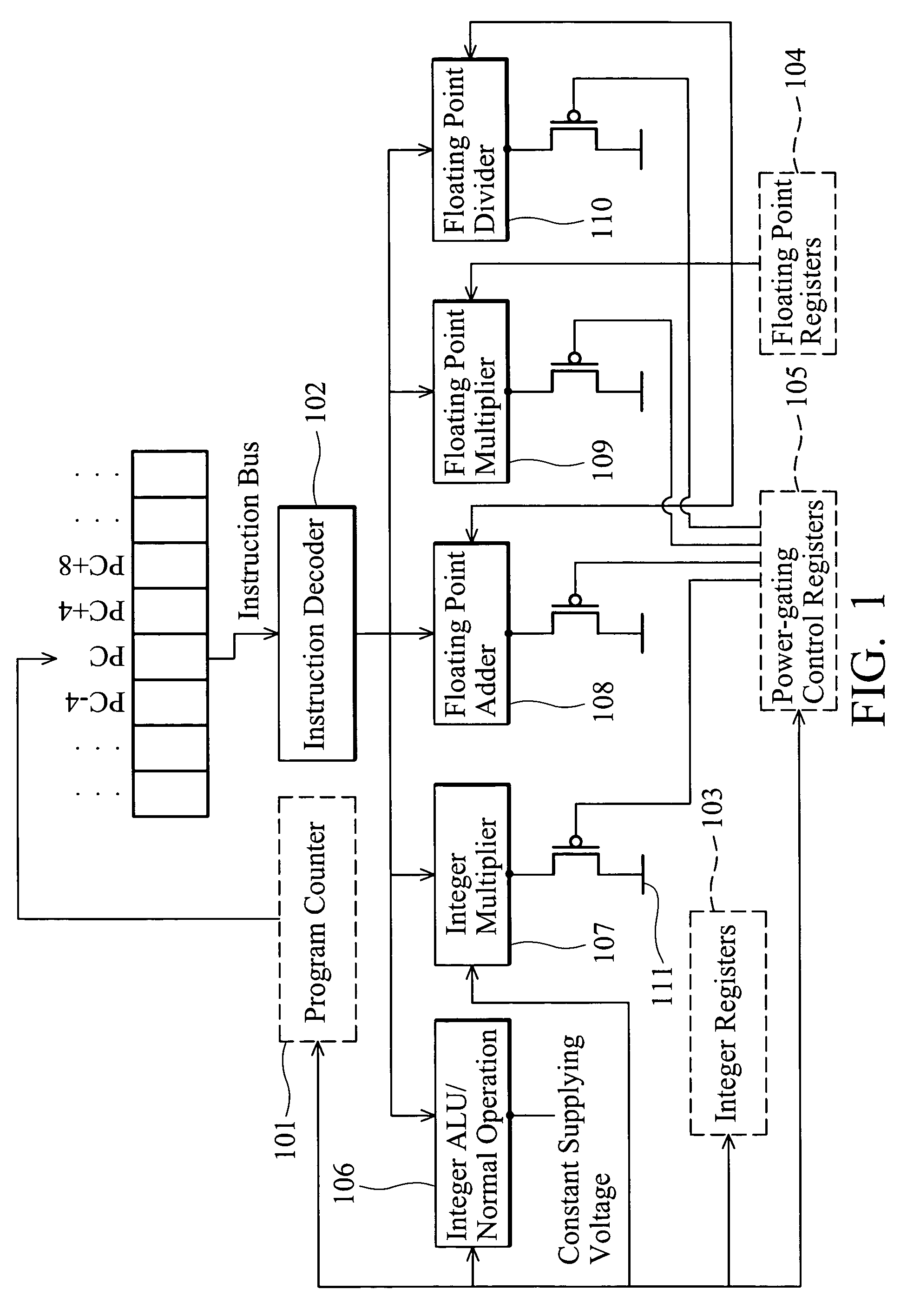
[0022]FIG. 1 shows architecture of a processor comprising a program counter 101, a instruction decoder 102, integer registers 103, floating point registers 104, power-gating control registers 105, an integer ALU 106, an integer multiplier 107, a floating point adder 108, a floating point multiplier 109, and a floating point divider 110. The power-gated components of the processor, comprising the integer multiplier 107, the floating point adder 108, the floating point multiplier 109, and the floating point divider 110, are equipped individually with a power-gating control unit 111 controlled by the value stored in the power-gating control registers 105. According to pow...


PUM


Abstract

A method of power-gating instruction scheduling for leakage power reduction comprises receiving a program, generating a control-flow graph dividing the program into a plurality of blocks, analyzing utilization of power-gated components of a processor executing the program, generating the first power-gating instruction placement comprising power-off instructions and power-on instructions to shut down the inactive power-gated components, generating the second power-gating instruction placement by merging the power-off instructions as one compound power-off instruction and merging the power-on instructions as one compound power-on instruction, and inserting power-gating instructions into the program in accordance with the second power-gating instruction placement.

Description

BACKGROUND OF THE INVENTION[0001]1. Field of the Invention[0002]The invention relates to a method of reducing power leakage in processors or ICs, and in particular to a method of power-gating instruction scheduling for power leakage reduction.[0003]2. Description of the Related Art[0004]Overall power dissipation in semiconductor application comprises static power dissipation and dynamic power dissipation, generated by current leakage and switching transient current in complementary metal oxides semiconductor (CMOS) circuits, respectively. As semiconductor technology continues to scale down to deep-submicron levels, power leakage gains more significance in the total power dissipation.[0005]In recent years, many power-gating mechanisms have been developed and employed to reduce the static power loss generated by the current leakage in CMOS circuits. The power-gating mechanisms insert power-gating instructions into a program to reduce power leakage of power-gated components in the proc...

Claims


Application Information

Patent Timeline
Patent Type & Authority Patents(United States)
IPC IPC(8): G06F1/32G06F1/00G06F9/45
CPCG06F1/3203
Inventor YOU, YI-PINGHUANG, CHUNG WENLEE, JENG KUENWANG, CHI-LUNGCHUANG, KUO YU
Owner IND TECH RES INST
Why Eureka
Try Eureka