
Powdered metal inlay

Inactive Publication Date: 2009-06-02
NOVATECH HLDG CORP
View PDF18 Cites 18 Cited by
  • Summary
  • Abstract
  • Description
  • Claims
  • Application Information

AI Technical Summary

Benefits of technology

[0036]Through use of a conforming adjustable sliding element; HIP pressure is applied to compress the radiused shell preform against a conforming substrate. The conforming adjustable sliding element and conforming substrate function together to substantially preserve the shape of the frusto-conical shell, including its predetermined edge radii, during HIP. To prevent metal carbides from contacting surfaces of the conforming adjustable sliding element and conforming substrate, these conforming surfaces (including their filleted areas corresponding to edge radii) and / or the radiused shell preform itself may in certain embodiments be coated substantially uniformly with at least one nonvolatile cement. Space around the radiused shell preform is evacuated without the need to totally enclose the preform and its substrate in a can (i.e., modified canning). Certain embodiments provide for leak testing of welded seals prior to application of HIP, and other embodiments make the use of welded seals unnecessary.
[0042]Note that when a circular ring is moved longitudinally within a circular depression to position a radiused shell preform between a conforming ring and a conforming depression bottom surface, or to redistribute metallic powder and compress it against the depression bottom surface to make a P / M preform, a back pressure may exist tending to move the ring away from the radiused shell or the powder. This back pressure may be resisted by, for example, applying pressure on the ring's reverse face that tends to move the ring toward the depression bottom. But maintaining such as pressure on the ring complicates normal handling of certain embodiments of the invention. In such cases, an alternative way to resist ring movement due to the back pressure is by creating an interference fit between the ring and the circular depression. Such an interference fit may be established between, for example, the internal diameter of the circular ring and the diameter of the cylindrical inner wall of the circular depression and / or the outer diameter of the ring and the diameter of the cylindrical outer wall of the circular depression. Because P / M preforms that are not sintered are relatively fragile or deformable when compared with a presintered or sintered radiused shell preform, the above interference fits may be used more often with nonsintered P / M preforms to minimize damage due to handling.
[0045]When the back pressure phenomenon noted above is counteracted by creating an interference fit of the circular ring within the circular depression, there will be a decreased tendency for handling to degrade a radiused shell or P / M preform within a valve seat assembly of the invention, even if force on the ring's reverse face is reduced to zero. Thus, creation of an interference fit between the circular ring and the circular depression facilitates handling in certain industrial environments and may be practiced, although it is not required for all embodiments of the invention.
[0046]Maintenance of a predetermined position of the circular ring within the circular depression allows production of consistent P / M preform shapes at lower pressures than those required for making conventional “green” metallic powder preforms. Even at relatively low pressures, metallic powder flows in a fluid-like manner to accommodate the changing shape of the internal space between the circular ring obverse face and the depression bottom surface. Meanwhile, the ring's interference fit in the depression prevents unplanned ring movement that could result in deformation of a P / M preform or displacement of (and possible damage to) a radiused shell preform.

Problems solved by technology

Presintering includes being heated sufficiently to cause a nonvolatile cement (e.g., cobalt, chromium and / or nickel) to adhere metal carbide particles in a predetermined shape, but not being heated sufficiently to cause the significant metallic grain growth that is associated with sintering.

Method used


Image

  • Powdered metal inlay
  • Powdered metal inlay
  • Powdered metal inlay

Examples


Embodiment Construction

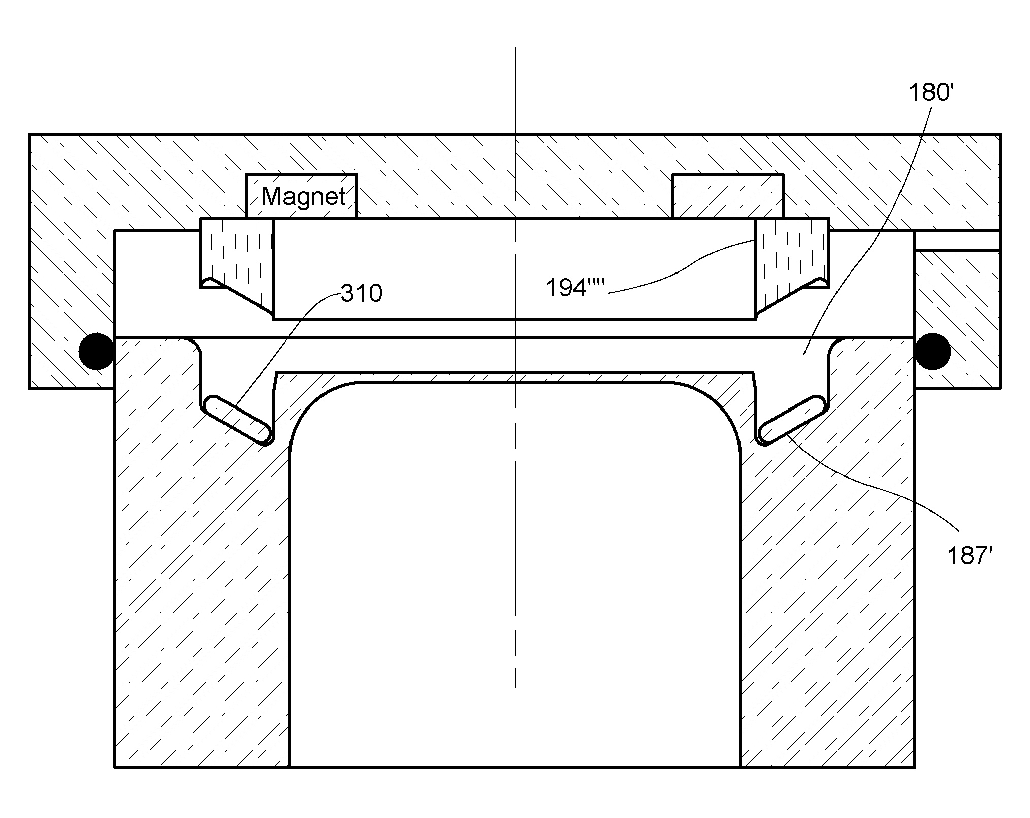
[0069]An exploded cross-sectional view of an example valve seat assembly 99 is schematically illustrated in FIG. 5. A valve seat form 96 comprises circular wall 170 which surrounds cylindrical void 172. Circular wall 170 is substantially symmetrical about its longitudinal axis and has a first end 174 spaced apart from a second end 176, as well as an inner surface 178 spaced apart from an outer surface 179. In this illustrated embodiment, a circular depression 180 lies between circular wall inner surface 178 and circular wall outer surface 179. Circular depression 180 extends from first end 174 of circular wall 170 toward second end 176 to depression bottom surface 187. Circular depression 180 comprises cylindrical inner depression wall 182 and cylindrical outer depression wall 184. Both inner depression wall 182 and outer depression wall 184 are coaxial with circular wall 170. Depression bottom surface 187 extends between inner depression wall 182 and outer depression wall 184. In v...


PUM

PropertyMeasurementUnit
Fractionaaaaaaaaaa
Fractionaaaaaaaaaa
Pressureaaaaaaaaaa

Abstract

Hot-isostatic-pressure (HIP) is used to make substantially nonporous cemented carbide inlays on metal substrates. A radiused shell preform typically comprising at least one metal carbide and at least one nonvolatile cement is shaped as a rigid frusto-conical shell having a substantially uniform thickness and a predetermined radius on every edge. HIP pressure is applied via a conforming adjustable sliding element to compress the preform against a conforming substrate. Surfaces of the conforming adjustable sliding element and conforming substrate, and / or the radiused shell preform, may in certain embodiments be coated substantially uniformly with at least one nonvolatile cement. Space around a radiused shell preform is evacuated without the need to totally enclose the radiused shell preform and its substrate in a can. Certain embodiments provide for leak testing of welded seals prior to application of HIP, and other embodiments make the use of welded seals unnecessary.

Description

FIELD OF THE INVENTION[0001]The invention relates generally to inlays comprising one or more metal carbides on metal substrates such as valve components.BACKGROUND[0002]Valve terminology varies according to the industry (e.g., pipeline or oil field service) in which the valve is used. In some applications, the term “valve” means just the valve body, which reversibly seals against the valve seat. In other applications, the term “valve” includes components in addition to the valve body, such as the valve seat and the housing that contains the valve body and valve seat. A valve assembly of the invention comprises a valve body and a corresponding valve seat, the valve body typically incorporating an elastomeric seal within a peripheral seal retention groove.[0003]Valve assemblies of the invention can be mounted in the fluid end of a high-pressure pump incorporating positive displacement pistons or plungers in multiple cylinders. Such valve assemblies typically experience high pressures ...

Claims


Application Information

Patent Timeline
IPC IPC(8): F16K51/00
CPCF04B53/102F04B53/1082F04B53/1087F16K1/465F16K31/041Y10T29/49297Y10S137/902Y10T29/49409Y10T29/49421B22F3/15B22F5/008B22F2003/153F16K15/06Y10T137/0491
Inventor BLUME, GEORGE H.
Owner NOVATECH HLDG CORP
Learn More