Continuous-time decision feedback equalizer

a feedback equalizer and continuous-time decision technology, applied in the field of digital filters, can solve the problems of poor signal-to-noise ratio (snr), poor reception signal level, and higher levels of crosstalk, so as to reduce temperamental interaction, simplify circuitry, and reduce cost. the effect of circuit power consumption and area

Active Publication Date: 2009-06-02
AVAGO TECH INT SALES PTE LTD
View PDF14 Cites 23 Cited by
  • Summary
  • Abstract
  • Description
  • Claims
  • Application Information

AI Technical Summary

Benefits of technology

[0019]The DFE of the present invention consumes less power, is of a more stable design, and overcomes the attenuation of high-frequencies and the low-bandpass filter problem of communication channels.
[0020]The present invention improves the state because the continuous time Infinite Impulse Response (IIR) feedback (e.g., in the general case the feedback of the outputs is used to calculate other output values) is a low-pass function. In some prior art there is employed a Finite Impulse Response (FIR) function that necessarily has to have higher bandwidth. Thus, in the same process technology, the circuit of the present invention can be made smaller and of lower power. This invention employs a different basis function that inherently spans multiple bit times, whereas some prior art needs to add circuitry for each additional bit time that needs to be corrected.
[0022]The DFE of the present invention may be thought of as a mixed signal solution employing a non-linear hybrid dynamical system with analog and discrete domains and memory, with the analog portion retaining more feedback information at a lower cost in terms of circuit power consumption and area than a purely digital DFE solution would employ.
[0023]The DFE of the present invention, in a preferred embodiment, preferably involves, in a portion of the circuit, a feedback filter in the continuous-time domain, which greatly simplifies the circuitry and helps reduce the temperamental interaction between the clock recovery PLL and the DFE, as compared to the FIG. 1 design.
[0024]Because the feedback filter in the DFE of the present invention is implemented as a continuous-time filter in a continuous-time feedback loop, the power consumed can be considerably reduced from that of a FIR-based and / or discrete-time DFE.
[0027]The sum total of all of the above advantages, as well as the numerous other advantages disclosed and inherent from the invention described herein, creates an improvement over prior techniques.

Problems solved by technology

This results in increasingly poorer receive signal levels and higher levels of crosstalk, among other problems.
This might be realized using a linear high pass filter, that boosts the high frequency signal was well any associated noise, and thus the signal-to-noise ratio (SNR) remains poor.
The negative feedback at summing circuit 3 has the effect of boosting the high-frequency content of the incoming signal, however, due to the digital, quantized nature of the feedback, the unwanted noise at the input is not boosted.
To meet this condition in the FIG. 1 DFE requires high bandwidth within the circuit and the circuit consumes much power.
While the bandwidth requirements can be alleviated for all taps except the h0 term by using a multi-phase architecture, this requires duplication of circuitry and thus requires more power and chip area to implement.

Method used


Image

  • Continuous-time decision feedback equalizer
  • Continuous-time decision feedback equalizer
  • Continuous-time decision feedback equalizer

Examples


Embodiment Construction

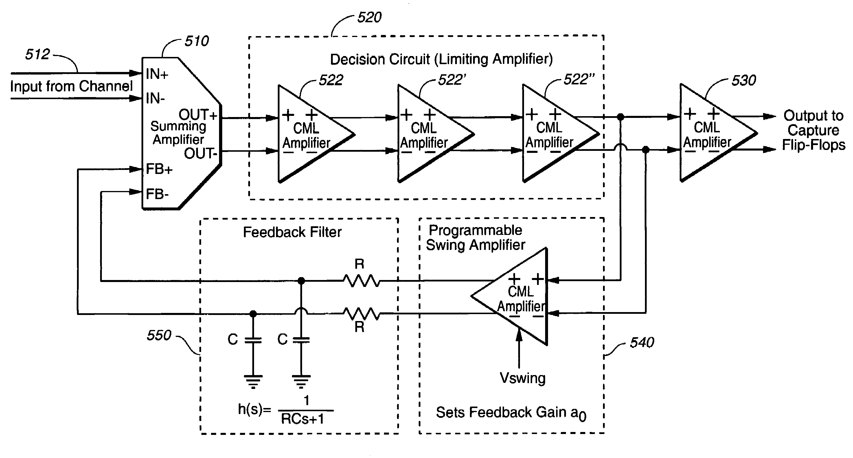
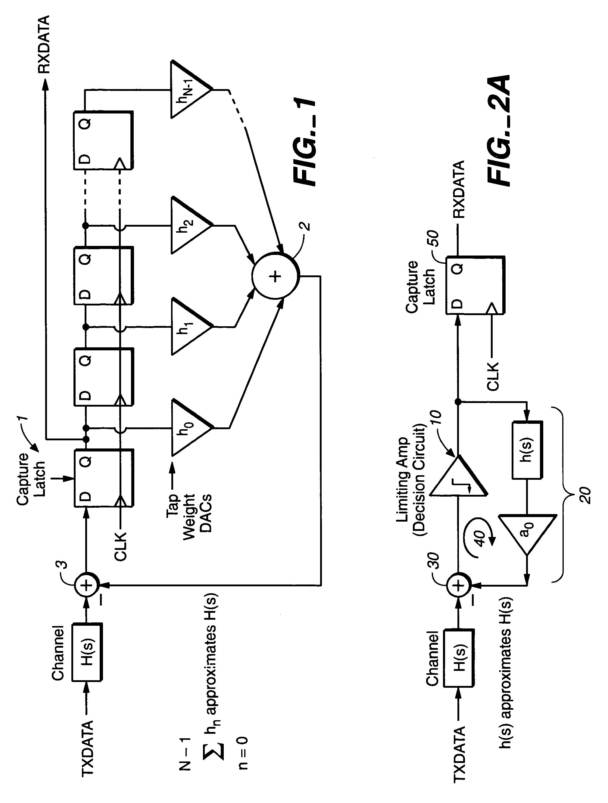
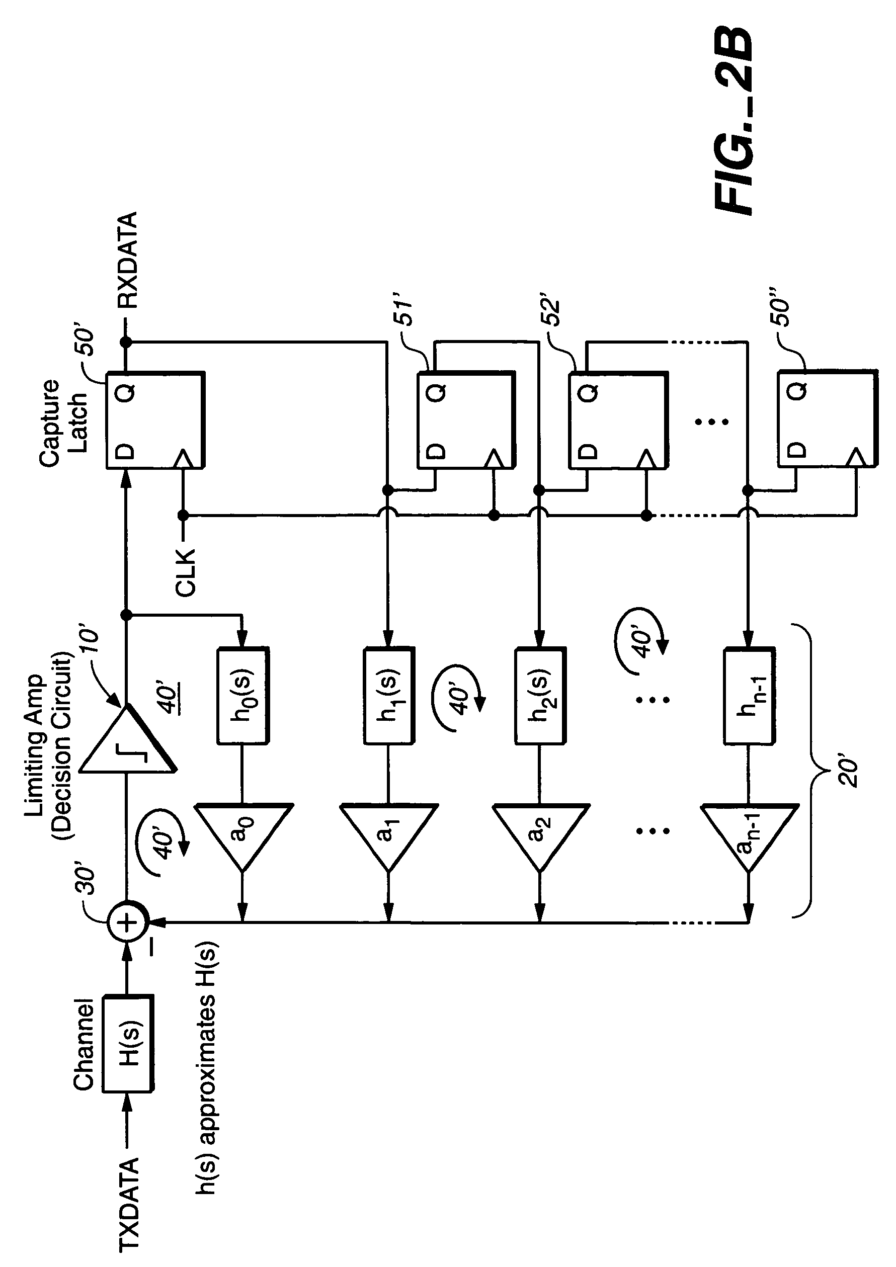
[0036]In all the preferred embodiments taught in the present invention, the DFE (Decision Feedback Equalizer) of the present invention operates a feedback loop that is in the continuous time domain, employing continuous-time active filters, and not employing discrete-time domain filters, such as digital FIR (Finite Impulse Response) filters or digital IRR (Infinite Impulse Response) filters. Because the filters in the DFE of the present invention operate in the continuous time domain and the DFE employs active filters (e.g., filters using transistors and amplifiers, such as op-amps), some of the problems associated with the FIG. 1 embodiment, such as synchronizing the clock domains between the equalizer and the capture flip-flop clocks are avoided. Other advantages of using active filters in the continuous time domain such as taught in the present invention, over a discrete time filter DFE scheme such as shown in FIG. 1, include: the elimination of potential aliasing problems, filte...


PUM


Abstract

A continuous-time domain Decision Feedback Equalizer (DFE) for use in a serial communication channel comprises in one embodiment a summer, a decision circuit, a capture flip-flop (FF) and an N-th order active filter. The DFE and its active filter operate in continuous time to give improved performance over a discrete-time DFE. In one embodiment involving a first-order active filter, the capture FF is outside the continuous-time negative feedback loop of the DFE and involves a differential signal amplifier. In another embodiment, the capture flip-flop is inside the DFE loop, and in a third embodiment the decision circuit comprises a comparator.

Description

BACKGROUND OF THE INVENTION[0001]1. Field of Invention[0002]The present invention relates generally to the field of digital filters in mixed-signal communication channels.[0003]2. Description of Related Art[0004]Signal processing in digital communications is concerned with optimizing performance given the constraints of power, noise, bandwidth limitations, area, memory, sampling limitations and numerous other requirements depending on the architecture employed.[0005]Data communication is moving away from parallel busses and towards serial transmission and serial protocols. System designers are under pressure to reliably send data over low bandwidth channels at rates for which they may not have been optimally designed for, and to pack more communication channels into smaller and smaller spaces. This results in increasingly poorer receive signal levels and higher levels of crosstalk, among other problems.[0006]To handle the low bandwidth channels, many receiver designs employ some sor...

Claims


Application Information

Patent Timeline
Patent Type & Authority Patents(United States)
IPC IPC(8): H03H7/30H03K5/159
CPCH04L25/03057H04L2025/03356H04L2025/0349
Inventor MARLETT, MARK JRUTHERFORD, MARK
Owner AVAGO TECH INT SALES PTE LTD
Why Eureka
Try Eureka