
Method of fabricating semiconductor device and semiconductor fabricated by the same method

a semiconductor and fabrication method technology, applied in the direction of semiconductor devices, basic electric elements, electrical appliances, etc., can solve the problems of increasing the total cost of fabricating display devices, inability to obtain sufficient electric field mobility, and high manufacturing cost, and achieve excellent crystallinity and simplified annealing process

Inactive Publication Date: 2009-06-09
SAMSUNG DISPLAY CO LTD
View PDF22 Cites 2 Cited by
  • Summary
  • Abstract
  • Description
  • Claims
  • Application Information

AI Technical Summary

Benefits of technology

This approach reduces manufacturing costs, maintains substrate integrity, and achieves high crystallinity of polycrystalline silicon, enabling efficient semiconductor device fabrication with improved electrical performance.

Problems solved by technology

The excimer laser annealing method may use a glass substrate since it is carried out at a crystallization temperature of about 450° C. However, manufacturing cost is high and the substrate is constrained in an optimal size, thereby increasing total cost to fabricate a display device.
However, since the solid phase crystallization method requires heating at a temperature of more than 600° C. for 20 or more hours for crystallization, many crystal defects are included in the crystallized polycrystalline silicon.
Accordingly, sufficient electric field mobility cannot be obtained, the substrate is prone to deform during an annealing process, i.e., a heat treatment process, and lowered crystallization temperature degrades productivity.
Because the solid phase crystallization method is also performed at high crystallization temperature, the glass substrate is not allowed to use.
Meanwhile, although the rapid thermal annealing (RTA) method may be accomplished in relatively short time, the substrate is prone to deform due to severe thermal shock and the crystallized polycrystalline silicon has poor electrical characteristics.
However, the foregoing conventional methods include the complicate processes of crystallizing the amorphous silicon and crystallizing the amorphous silicon again while the impurity region is activated at a high temperature.

Method used


Image

  • Method of fabricating semiconductor device and semiconductor fabricated by the same method
  • Method of fabricating semiconductor device and semiconductor fabricated by the same method
  • Method of fabricating semiconductor device and semiconductor fabricated by the same method

Examples


first embodiment

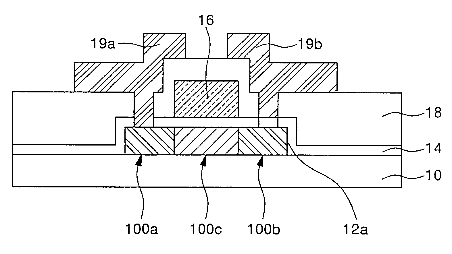
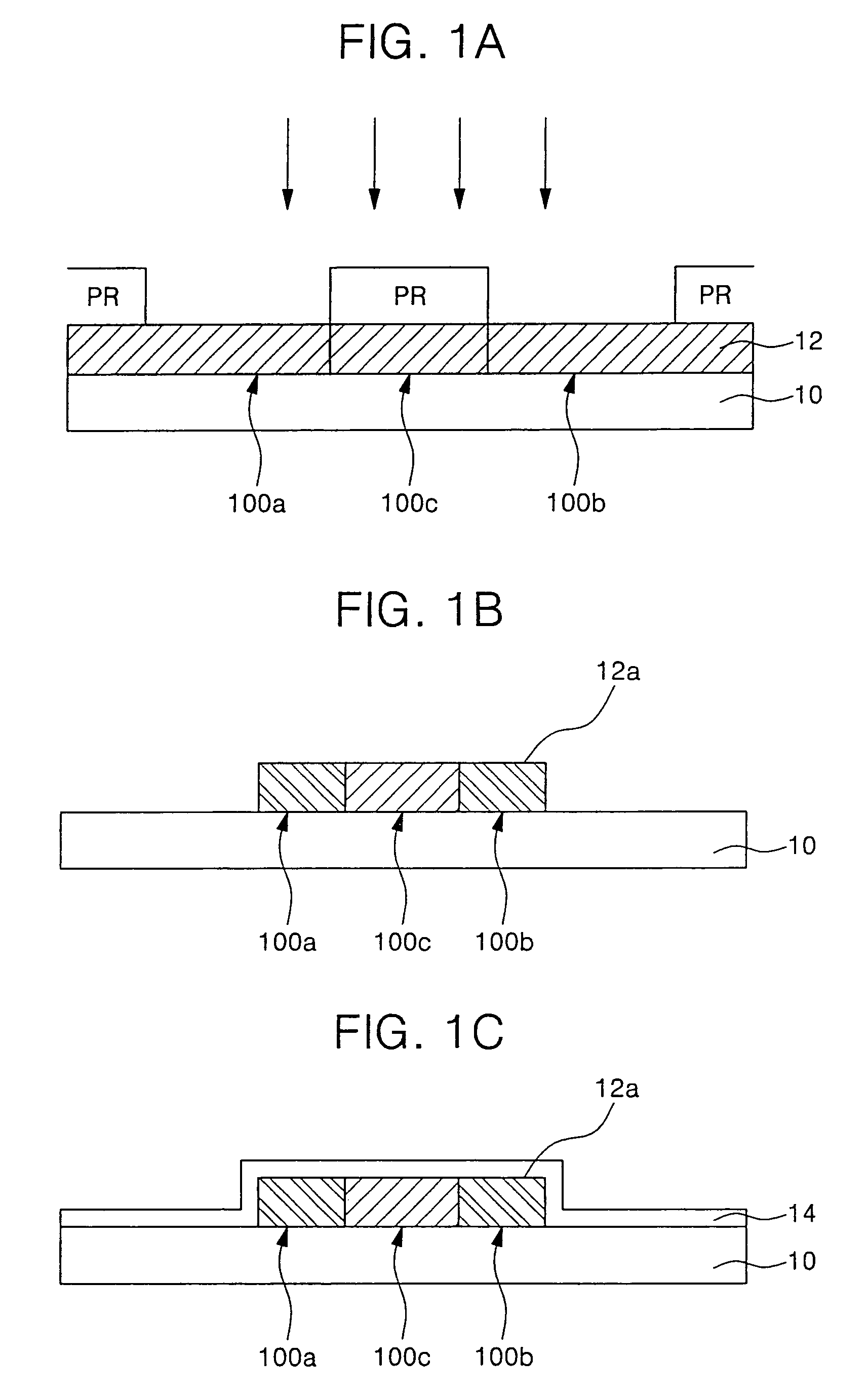
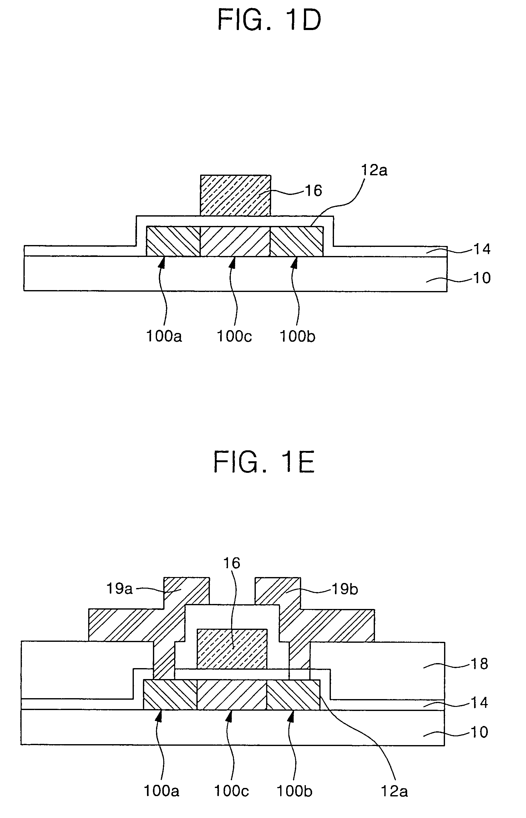
[0024]FIGS. 1A to 1E sequentially illustrate a method of fabricating a semiconductor device according to the present invention in sequence.

[0025]Referring to FIG. 1A, amorphous silicon or a silicon layer 12 containing a great quantity of amorphous silicon is deposited on a substrate 10. Here, the substrate 10 is generally formed of a transparent glass substrate.

[0026]Further, the silicon layer 12 may be deposited by a typical deposition method such as a plasma enhanced chemical vapor deposition (PECVD) method, a low-pressure chemical vapor deposition (LPCVD) method, or the like.

[0027]Additionally, a buffer layer such as a silicon nitride (SiNx) layer or a silicon oxide (SiO2) layer may be interposed between the substrate 10 and the amorphous silicon layer 12 prior to depositing the amorphous silicon layer, in order to prevent contaminants or the like created in the substrate from diffusing into the silicon layer 12 or enhance interfacial characteristics between the silicon layer 12 ...

second embodiment

[0042]FIGS. 2A to 2D sequentially illustrate a method of fabricating a semiconductor device according to the present invention.

[0043]Referring to FIG. 2A, a gate electrode 26 is patterned on a substrate 20. Here, the substrate 10 is generally formed of a transparent glass substrate.

[0044]Additionally, a buffer layer such as SiNx or SiO2 may be formed on the substrate 20 in order to prevent contaminants or the like created in the substrate from diffusing into the gate electrode 26 or enhance interfacial characteristics between the gate electrode 26 and the substrate 20.

[0045]Then, as shown in FIG. 2B, an inorganic insulating layer such as SiO2 or SiNx is formed as a gate insulating layer 24 over the entire surface of the substrate 20 having the gate electrode 26. Subsequently, amorphous silicon or a silicon layer 22 containing a great quantity of amorphous silicon is deposited on the gate insulating layer 24.

[0046]Here, the silicon layer 22 may be deposited by a general deposition me...


PUM

PropertyMeasurementUnit
temperatureaaaaaaaaaa
pressureaaaaaaaaaa

Abstract

A semiconductor device and method of fabricating the same are provided. The method includes: depositing a silicon layer containing amorphous silicon on a substrate; defining source and drain regions by doping the silicon layer with impurity ions; crystallizing the amorphous silicon by an annealing process under an atmosphere of H2O at a predetermined temperature, and at the same time activating the impurity ions to form a semiconductor layer; forming a gate insulating layer over the entire surface of the substrate having the semiconductor layer; and forming a gate electrode on the gate insulating layer in correspondence with a channel region of the semiconductor layer, in which the annealing process is simplified by crystallizing the polycrystalline silicon and at the same time activating the impurity ions, thereby preventing the substrate from being deformed due to high temperature during the annealing process.

Description

CLAIM OF PRIORITY[0001]This application makes reference to, incorporates the same herein, and claims all benefits accruing under 35 U.S.C. §119 from an application entitled METHOD OF FABRICATING SEMICONDUCTOR DEVICE AND SEMICONDUCTOR FABRICATED BY THE SAME METHOD filed with the Korean Industrial Property Office on 5 Jul. 2004 and there duly assigned Serial. No. 2004-52054.BACKGROUND OF THE INVENTION[0002]1. Field of the Invention[0003]The present invention relates to a method of fabricating a semiconductor device and a semiconductor device fabricated by the same method, and more particularly, to a method of fabricating a semiconductor device which is capable of crystallizing polycrystalline silicon with excellent crystallinity and preventing a substrate from being bent due to a high crystallization temperature upon crystallization, and a semiconductor device fabricated by the same method.[0004]2. Description of the Related Art[0005]Polycrystalline silicon is used in an active device...

Claims


Application Information

Patent Timeline
Patent Type & Authority Patents(United States)
IPC IPC(8): H01L21/20H01L21/335
CPCH01L21/2022H01L29/66757H01L29/66765H01L21/02686H01L21/02422H01L21/02488H01L21/02532H01L21/02667H01L21/02595
Inventor KAKKAD, RAMESHKIM, YONG-SEOG
Owner SAMSUNG DISPLAY CO LTD
Learn More