Method and apparatus for performing model based placement of phase-balanced scattering bars for sub-wavelength optical lithography

a technology of phase-balanced scattering and sub-wavelength optical lithography, applied in the field of photolithography, can solve the problems of reducing the size of an integrated circuit, the critical dimension of its corresponding mask pattern approaching the resolution limit of the optical exposure tool, and the process becomes more difficult, so as to prevent the reduction of the latitude of the printing process for the main design features

Active Publication Date: 2009-06-23
ASML NETHERLANDS BV
View PDF26 Cites 23 Cited by
  • Summary
  • Abstract
  • Description
  • Claims
  • Application Information

AI Technical Summary

Benefits of technology

[0014]In an effort to solve the foregoing needs, it is one object of the present invention to provide a systemic method of implementation for automatically applying the phase-balanced SB features to a mask design based on the interference map associated with the given mask design utilizing a model-based approach. Further, it has been determined that non-printable 0-phase SB features must be balanced with non-printable π-phase SB features in order to ensure the non-printability of the 0-phase SB features, and to prevent a reduction in the printing process latitude for the main design features. The model-based approach of the present invention allows provides for the placement of such π-phase SB features.
[0021]The method of the present invention provides important advantages over the prior art. Most importantly, the method of the present invention provides a systemic method for automatically applying the phase-balanced SB features to a mask design based on the interference map associated with the given mask design utilizing a model-based approach. The application of the phase-balanced assist features in accordance with the present invention, allows for the benefit of enhanced imaging of the target features, while preventing a degradation in the process window, by minimizing the likelihood hood that the assist features enhancing the imaging of the target features will be imaged by placing additional assist features having an opposite phase in the mask layout so as to phase balance the assist features enhancing the imaging of the target features.

Problems solved by technology

These rules are set by processing and design limitations.
As the size of an integrated circuit is reduced and its density increases, however, the CD (critical dimension) of its corresponding mask pattern approaches the resolution limit of the optical exposure tool.
Patterning IC device features with size and pitch dimensions well below exposure wavelength on the resist-coated wafers with sufficient process latitude has become a significant manufacturing challenge today.
With unforeseen economical and technical challenges for the next generation lithography, the semiconductor industry has become more interested in extending the existing exposure wavelength technology.
The lower k1, the more difficult the process becomes.
However, in order to meet the printing performance requirement for pitch features at sub-wavelength for any two-dimensional (2D) features such as contact or via holes, it is currently not possible to achieve satisfactory printing performance based on the existing rule-based methods.
This is due to the fact that it is extremely difficult to apply a rule-based approach to achieve optimum placement of SBs for enhancing, for example, the printing of sub-wavelength pitch contact holes.
While the concept has been demonstrated feasible for manufacturing purposes, it can still be a challenging process to apply the concepts into a manufacturing worthy implementation, especially when dealing with complex mask designs.

Method used


Image

  • Method and apparatus for performing model based placement of phase-balanced scattering bars for sub-wavelength optical lithography
  • Method and apparatus for performing model based placement of phase-balanced scattering bars for sub-wavelength optical lithography
  • Method and apparatus for performing model based placement of phase-balanced scattering bars for sub-wavelength optical lithography

Examples


Embodiment Construction

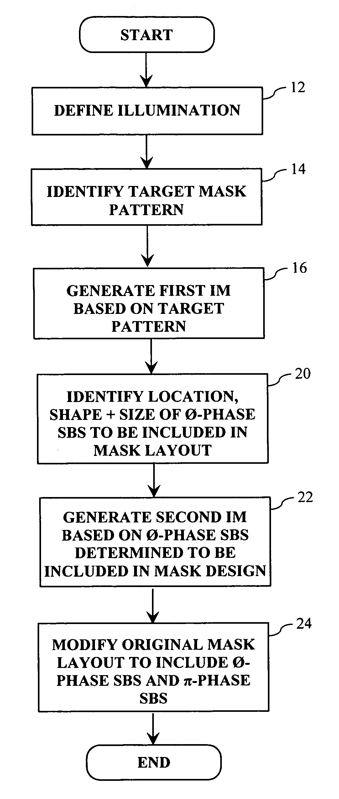
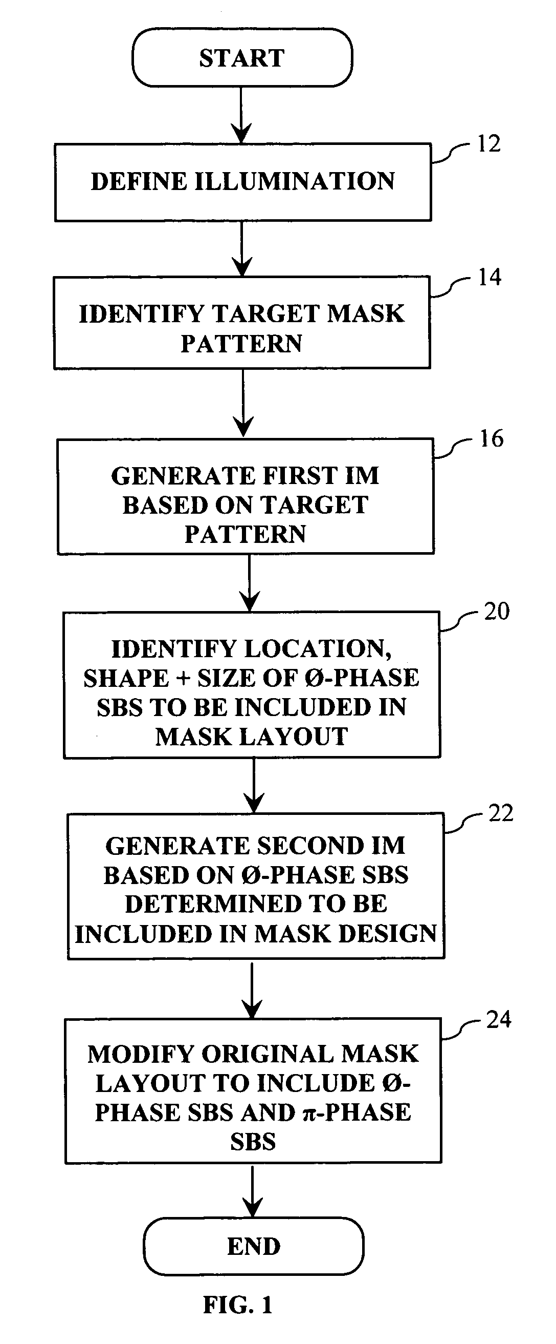
[0038]As explained in more detail below, the OPC technique of the present invention allows for a full-pitch range of deep sub-wavelength mask patterns to be imaged utilizing substantially any illumination condition. In general, the OPC technique entails generating an interference map (IM) based on the mask design (i.e., target pattern), which indicates how each point in the field surrounding the desired target pattern interacts with the target pattern. The possibilities are that a given point either constructively interferes, destructively interferes or is neutral (i.e., neither constructive or destructive interference) with respect to the target pattern. Once the IM is generated, it is utilized to determine where 0-phase assist features (i.e., SBs) are positioned in the mask design so as to enhance the imaging of the target features. Next, a second IM is generated based on the placement of the 0-phase assist features, which indicates how each point in the field surrounding the 0-ph...


PUM

PropertyMeasurementUnit
wavelengthaaaaaaaaaa

Abstract

A method of generating a mask design having optical proximity correction features disposed therein. The methods includes the steps of obtaining a desired target pattern having features to be imaged on a substrate; determining a first interference map based on the target pattern, which defines areas of constructive interference between at least one of the features to be imaged and a field area adjacent the at least one feature; placing a first set of assist features having a first phase in the mask design based on the areas of constructive interference defined by the first interference map; determining a second interference map based on the first set of assist features, which defines areas of constructive interference between assist features of the first set of assist features and a field area adjacent at least one of the assist features of the first set of assist features; and placing a second set of assist features having a second phase in the mask design based on the areas of constructive interference defined by the second interference map, wherein the first phase does not equal the second phase.

Description

CLAIM OF PRIORITY[0001]This patent application, and any patent(s) issuing therefrom, claims priority from U.S. provisional patent application No. 60 / 500,260, filed on Sep. 5, 2003, entitled “A Model Based Placement of Phase-Balanced Scattering Bars to Achieve Lithography Patterning Requirements for Sub-wavelength Pitch Features” which is incorporated herein by reference in its entirety.FIELD OF THE INVENTION[0002]The present invention relates to photolithography, and in particular relates to a method of applying optical proximity correction features to mask layouts utilizing an interference map. In addition, the present invention relates to a device manufacturing method using a lithographic apparatus comprising a radiation system for providing a projection beam of radiation; a mask table for holding a mask, serving to pattern the projection beam; a substrate table for holding a substrate; and a projection system for projecting the patterned projection beam onto a target portion of t...

Claims


Application Information

Patent Timeline
Patent Type & Authority Patents(United States)
IPC IPC(8): G03F1/02G03F1/00G03F1/36G03F9/00G06F17/50H01L21/027
CPCG03F1/144G03F1/36G03F7/705G03F1/26
Inventor SHI, XUELONGCHEN, JANG FUNGLAIDIG, THOMASWAMPLER, KURT E.VAN DEN BROEKE, DOUGLAS
Owner ASML NETHERLANDS BV
Why Eureka
Try Eureka