Optical fiber

a technology of optical fiber and optical fiber, applied in the field of optical fiber transmission, can solve the problems of loss, transmitter instability, and reduced signal-to-noise ratio at the receiver

Active Publication Date: 2009-06-30
DRAKA COMTEQ BV
View PDF40 Cites 394 Cited by
  • Summary
  • Abstract
  • Description
  • Claims
  • Application Information

AI Technical Summary

Problems solved by technology

One limitation for use of such optical fibers for telecommunication applications is loss due to stimulated Brillouin scattering (SBS).
Thus, SBS reduces the signal-to-noise ratio at the receiver and can cause the transmitter to become unstable as a result of the entry of reflected light.
Some disadvantages of changing the index of refraction along the axial direction of the fiber, and tight fiber wrapping, include non-uniform fiber properties (e.g., splicing characteristics, Raman gain, and cut-off wavelength) along the fiber length and increased fatigue, which impacts optical fiber life.
Coefficients of thermal expansion and viscosity control in alternating layers are hard to achieve, and manufacturing processes capable of obtaining a preform of doped and undoped layers within the core requires costly equipment.
Moreover, whenever the core is doped, fiber losses increase.
Such sharp variations will induce silica network defects at its interfaces, causing increased absorption loss of the fiber and degraded aging behavior.
Such an optical fiber is difficult to achieve, however, as the optical fiber refractive index profile must simultaneously satisfy good light guiding and bad acoustic guiding.
In trying to reduce SBS in this way, drawbacks in optical transmission properties are expected.
Trapezoid profile shapes, however, might not be well suited for certain telecommunication applications.
The fiber refractive index profile disclosed in this document might not be well suited for certain telecommunication applications.
Moreover, high optical power in transmission optical fibers may damage the fiber coating and thus accelerate aging of the optical fiber wherever bends are present.
That notwithstanding, a reduction in the MAC value by reducing the mode field diameter and / or by increasing the effective cut-off wavelength may lead to noncompliance with the G.652 standard, making the optical fiber commercially incompatible with some transmission systems.
Compliance with the G.652 standard while reducing bending losses and increasing SBS threshold is a challenge for fiber applications in which single access optical fibers are to be used both in long-haul transmission systems and in Fiber-to-the-Home (FTTH) or Fiber-to-the-Curb (FTTC) systems.
This reduction in mode field diameter, however, leads to overstepping the G.652 standard.
The cost of manufacturing this fiber and its high attenuation levels (>0.25 dB / km) reduce its commercial viability in FTTH systems.
U.S. Pat. No. 6,771,865 fails to disclose sufficient information to determine whether its disclosed fiber meets the G.652 standard.
This disclosed fiber, however, has a chromatic dispersion that does not meet the G.652 criteria.
International Application No. 2004 / 092794 fails to identify the problems of microbending losses and Brillouin scattering.

Method used


Image

  • Optical fiber
  • Optical fiber
  • Optical fiber

Examples


Embodiment Construction

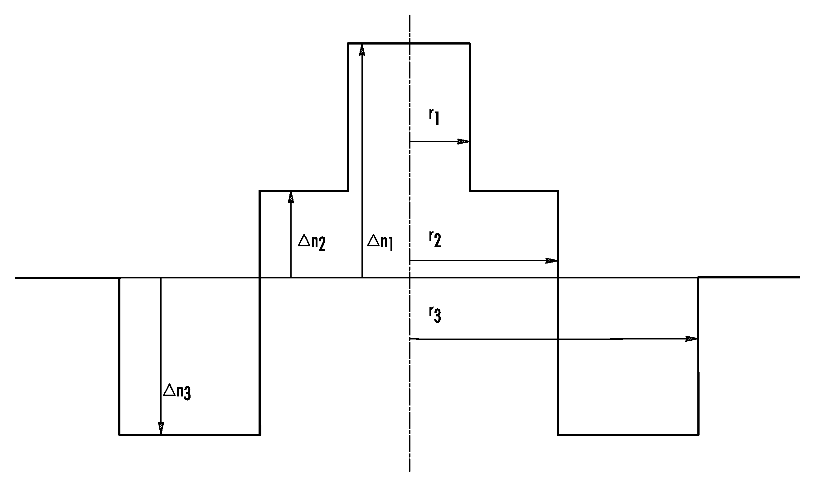
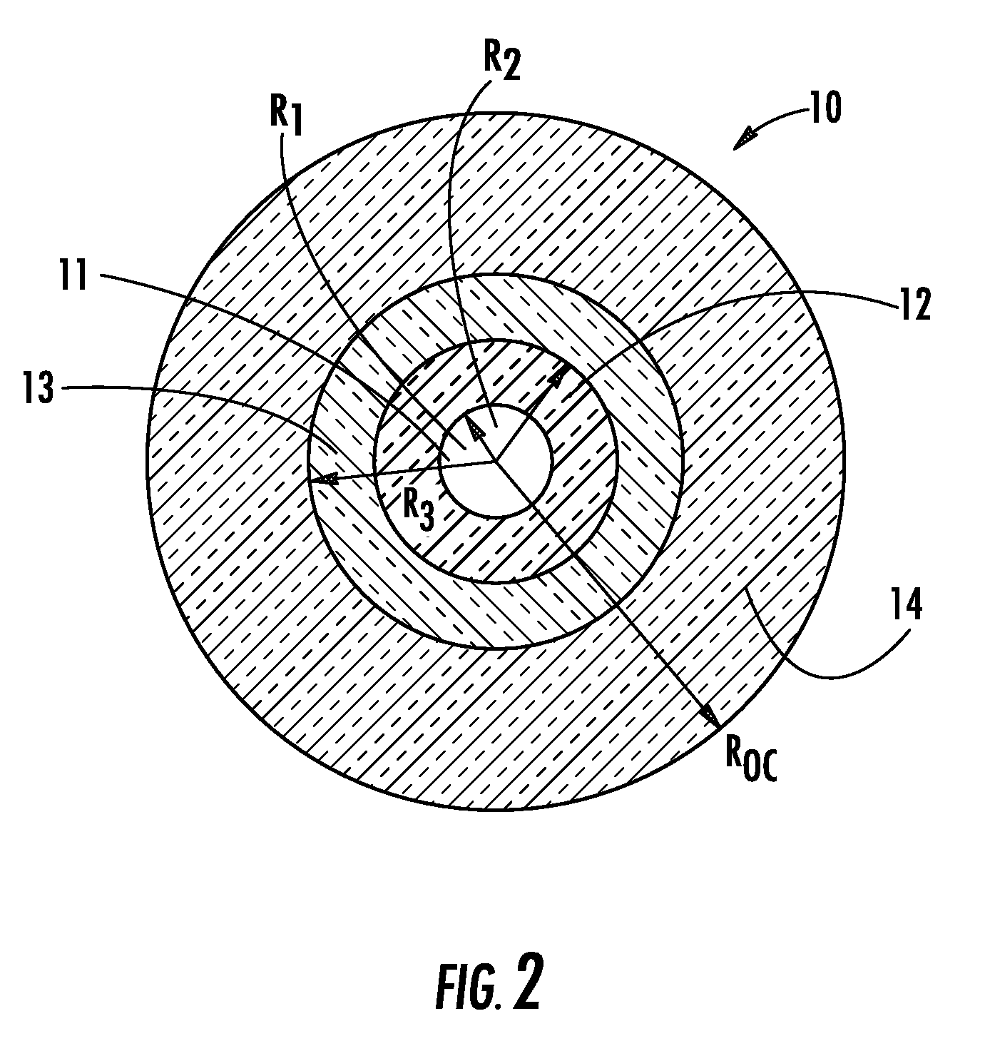
[0069]In one aspect (and with reference to FIG. 2), the present invention embraces an optical fiber 10 that includes a core 11 (i.e., the central core region in which the optical signal to be transmitted is guided) and a cladding region for confining the optical signal in the core 11. The cladding region includes a first inner cladding 12, a depressed trench 13 (or depressed, second inner cladding), and an outer cladding 14 (e.g., an external optical cladding). The depressed trench 13 typically has a refractive index difference with the outer cladding 14 that is less than −3×10⁻³ (e.g., less than about −15×10−3).

[0070]According to the present invention, the core region of the optical fiber includes at least two dopants, the concentrations of which, in effect, vary continuously over the entire radius of the core region. Typically, the substantially continuous variation in radial dopant concentration is progressive (e.g., increasing continuously in a radial direction) or regressive (e...


PUM


Abstract

An improved optical fiber achieves both reduced bending and microbending losses, as well as a much higher Brillouin threshold, as compared to standard transmission fibers. The optical fiber comprises a core including at least two dopants and having a refractive index difference Δn1 with an outer optical cladding, a first inner cladding having a refractive index difference Δn2 with the outer cladding, and a depressed, second inner cladding having a refractive index difference Δn3 with the outer cladding of less than −3×10⁻³. The radial concentration of at least one of the core dopants varies continuously over the entire core region of the optical fiber.

Description

CROSS-REFERENCE TO PRIORITY APPLICATION[0001]This application claims the benefit of pending European Application No. 06291866.9 (filed Dec. 4, 2006, at the European Patent Office), which is hereby incorporated by reference in its entirety.FIELD OF THE INVENTION[0002]The invention relates to the field of optical fiber transmission and, more specifically, to an optical fiber having reduced losses due to stimulated Brillouin scattering (SBS) and reduced bending and microbending losses.BACKGROUND OF THE INVENTION[0003]A refractive index profile of an optical fiber is a graphical representation of the value of the refractive index as a function of optical fiber radius. Conventionally, the distance r to the center of the fiber is shown along the abscissa, and the difference between the refractive index and the refractive index of the fiber cladding is shown along the ordinate axis. The optical fiber refractive index profile is referred to as a “step” profile, a “trapezoidal” profile, a “p...

Claims


Application Information

Patent Timeline
Patent Type & Authority Patents(United States)
IPC IPC(8): G02B6/36
CPCG02B6/03694G02B6/0365
Inventor FLAMMER, IVODE MONTMORILLON, LOUIS-ANNEMATTHIJSSE, PIETER
Owner DRAKA COMTEQ BV
Why Eureka
Try Eureka