Purification works for thermal power plant

a technology for purification works and thermal power plants, applied in the direction of emissions prevention, separation processes, lighting and heating apparatus, etc., can solve the problems of high cost of cleaning plants, low efficiency, and high cost of long-term and expensive development, so as to reduce heat loss in the system and increase the energy yield of plants

Inactive Publication Date: 2009-07-14
CO2 CAPSOL
View PDF14 Cites 97 Cited by
  • Summary
  • Abstract
  • Description
  • Claims
  • Application Information

AI Technical Summary

Benefits of technology

[0040]According to an embodiment, the plant also comprises heat exchangers for heating the CO2 poor stream by heat exchanging against the exhaust gas from the combustion chamber before the CO2 poor stream is expanded over turbine(s). Heating the exhaust gas increases the energy yield from the plant and thus reduces the heat loss in the system.

Problems solved by technology

Still, relatively little development work is carried out to capture CO2, the methods presented up till now are characterized either by low efficiency or by a need for much long-term and expensive development.
The main problem with this technology is that one operates with a low partial pressure of CO2, typically 0.04 bar, in the gas which shall be cleaned.
The cleaning plant becomes expensive and the degree of cleaning and size of the power plant are limiting factors.
The effect of this is very limited due to the properties of the turbine, among other things.
An essential disadvantage is that the partial pressure of oxygen in the gas also becomes high, for example 1.5 bar, while amines typically degrade quickly at oxygen partial pressures above about 0.2 bar.
In addition, costly extra equipment is required.
However the total costs for such a system becomes relatively high, as one must have a substantial plant for production of oxygen in addition to the power plant.
Production and combustion of pure oxygen represent considerable safety challenges, in addition to great demands on the material.
The total plant becomes complicated and expensive, as it comprises a hydrogen-generating plant and a power plant.
In addition, alternative methods are characterized by long-term, expensive and risky developments, with a typical time frame of 15 years research and a further 5 to 10 years or more before operating experience is attained.
An extended time frame is environmentally very undesirable.

Method used


Image

  • Purification works for thermal power plant
  • Purification works for thermal power plant
  • Purification works for thermal power plant

Examples


example 1

CO2 Removal from a One Stage Gas Power Plant

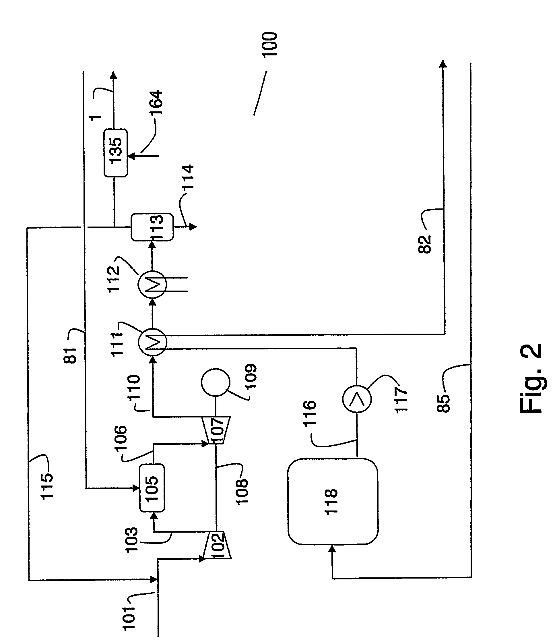
[0094]FIG. 2 illustrates a one stage thermal gas power plant 100. Natural gas is taken out from the gas inlet 9 (FIG. 1) and, after heating in heat exchanger 80, led to the power plant 100 in a line 81 and introduced into a combustion chamber 105.

[0095]Air is introduced into the system through an air intake 101, compressed in a compressor 102 and led to the combustion through a line 103. The combustion gases from the combustion chamber 105 are led through a line 106 to a gas turbine 107, where the gas is expanded. The combustion chamber 105 and line 106 are illustrated as separate units but is normally integrated in the gas turbine 107. The compressor 102, the gas turbine 107 and a generator 109 for generation of electrical power are preferably mounted on a common shaft 108.

[0096]The expanded combustion gas from the gas turbine 107 is led through a line 110 via heat exchangers illustrated by heat exchanger 111 and trim cooler 112 before th...

example 2

CO2 Removal from a Two Stage Gas Power Plant

[0103]FIG. 3 illustrates a two stage thermal gas power plant. The elements corresponding to the elements described in Example 1 and illustrated in FIG. 2 have the same reference numbers and are not described again here unless regarded as necessary.

[0104]The flue gas leaving the first stage, corresponding to the thermal gas power plant in FIG. 2, is split into a recirculation line 115, as in FIG. 2, and secondary air line 120. It is also possible to omit recirculation line 115, and instead balance the flue gas rate from 113 and the volume flow requirement in line 120 by means of a not shown air inlet mixing box similar to 135. The exhaust gas from the first stage in the secondary air line 120 is introduced into the second stage, compressed in a compressor 121 and led to a combustion chamber 123 through a line 122. Natural gas in line 81 is introduced through line 81B as additional fuel into the combustion chamber 123.

[0105]The combustion ga...

example 3

CO2 Removal from a Thermal Coal Fired Power Plant

[0110]An exemplary plant is illustrated in FIGS. 4 and 5. FIG. 4 illustrates a combined thermal gas power plant and CO2 removal unit, and FIG. 5 illustrates a coal fired thermal power plant to be coupled with the plant at FIG. 4.

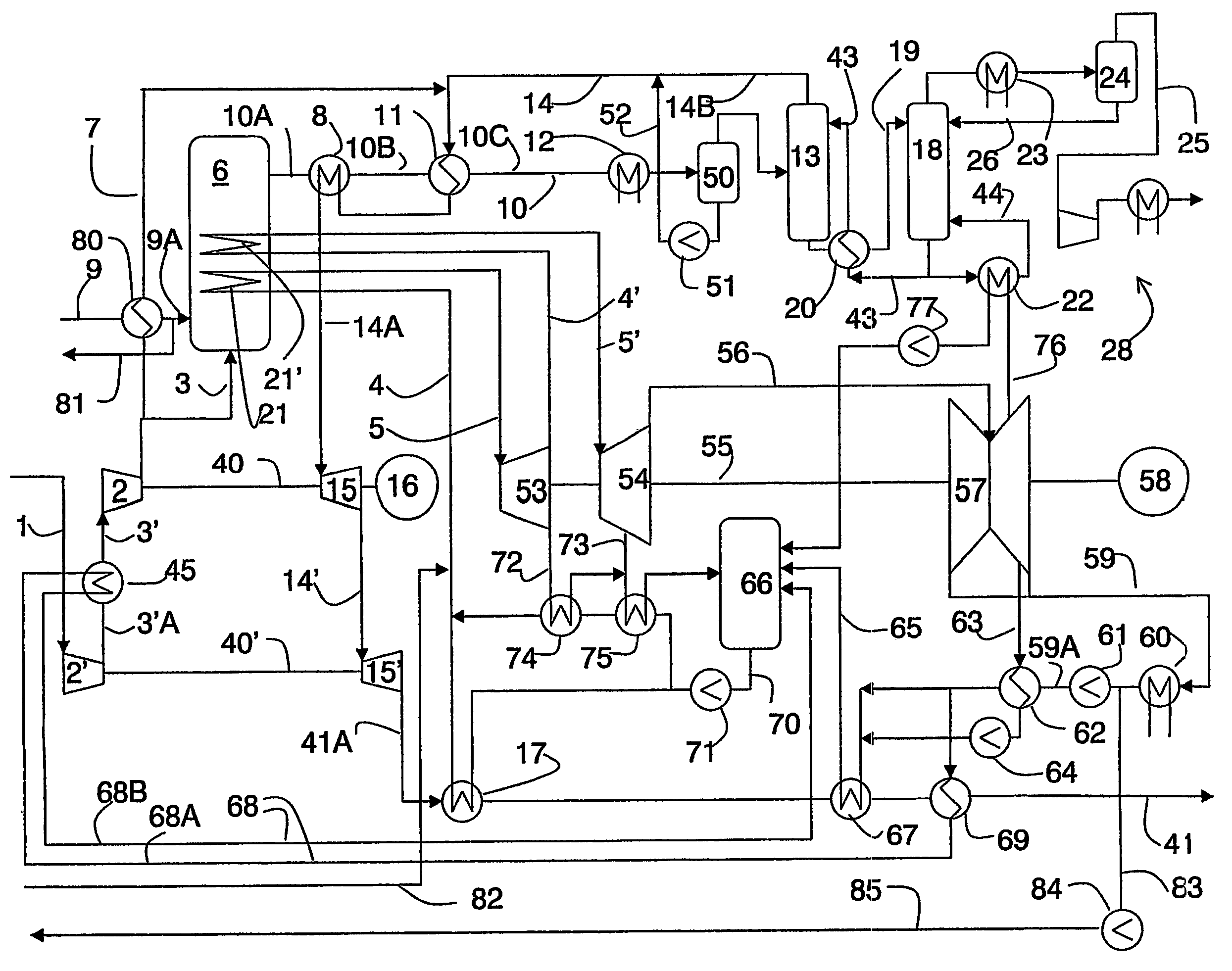
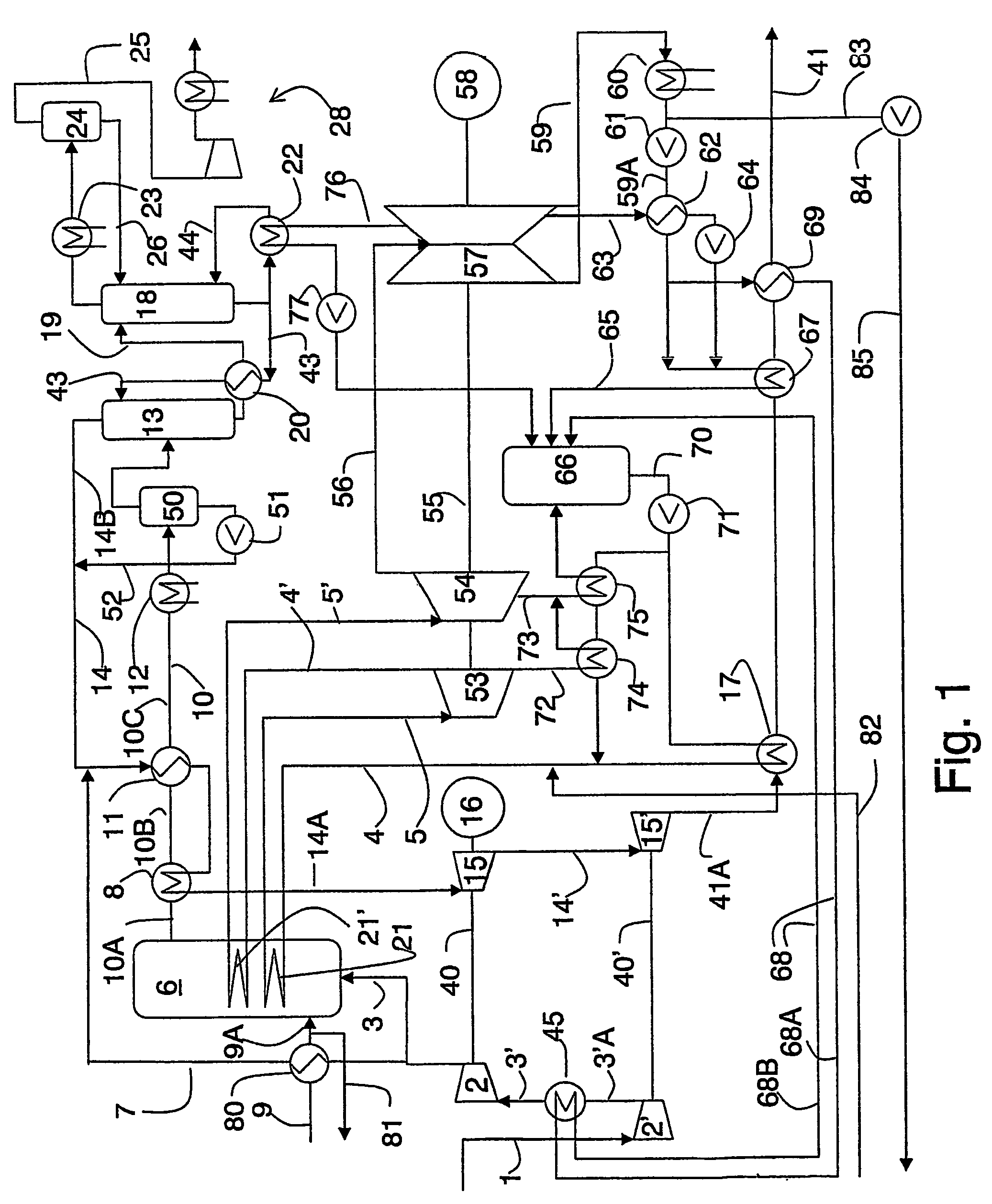
[0111]The plant according to FIG. 4 corresponds to the plant of FIG. 1 wherein lines 81, 82, 83, 85 and the pump 84 are removed and lines 87A and 87B and a heat exchanger 86 is inserted. The heat exchanger 86 heats incoming water in line 87A and cools the exhaust gas in line 41. The heated water leaves the heat exchanger in line 87B.

[0112]Carbon fuel is introduced from a coal line 150 into a combustion chamber 149 wherein the coal is combusted by introduction of air from a air feed line 151. The air in the air feed line is preferably preheated by heat exchanging in a heat exchanger 152 against the hot combustion gas leaving the combustion chamber 149 in combustion line 153.

[0113]The combustion gases leaving th...


PUM

PropertyMeasurementUnit
temperatureaaaaaaaaaa
mean temperatureaaaaaaaaaa

Abstract

A method for separation of CO2 from the combustion gas from a thermal power plant fired with fossil fuel, wherein the combustion gas from the thermal power plant is used as cooled, compressed and reheated by combustion of natural gas in a combustion chamber to form an exhaust gas, where the exhaust gas is cooled an brought in contact with an absorbent absorbing CO2 from the exhaust gas to form a low CO2 stream and an absorbent with absorbed CO2, and where the low CO2 stream is heated by means of heat exchanges against the hot exhaust gas leaving the combustion chamber before it is expanded in turbines, is described. A plant for performing the method and a combined plant is also described.

Description

FIELD OF THE INVENTION[0001]The present invention relates to a method for separation of the combustion gas from a thermal power plant fired by a fossil fuel into a CO2 rich and a CO2 poor stream, a separation plant for performing the method and a combined plant comprising a thermal power plant fired by a fossil fuel and the present separation plant.BACKGROUND OF THE INVENTION[0002]The concentration of CO2 in the atmosphere has increased by nearly 30% in the last 150 years. The concentration of methane has doubled and the concentration of nitrogen oxides has increased by about 15%. This has increased the atmospheric greenhouse effect, something which has resulted in:[0003]The mean temperature near the earth's surface has increased by about 0.5° C. over the last one hundred years, with an accelerating trend in the last ten years.[0004]Over the same period rainfall has increased by about 1%[0005]The sea level has increased by 15 to 20 cm due to melting of glaciers and because water exp...

Claims


Application Information

Patent Timeline
Patent Type & Authority Patents(United States)
IPC IPC(8): F23J15/04F01K23/08B01D53/14B01D53/62F23J15/00F23J15/08
CPCB01D53/1475B01D53/62F01K23/08F23J15/006F23J15/08F23J15/04B01D2257/504Y02C10/06F23J2215/50F23J2219/40Y02C10/04Y02A50/20Y02C20/40Y02E20/32
Inventor FLEISCHER, HENRIKCHRISTENSEN, TORBORSETH, KNUT
Owner CO2 CAPSOL
Why Eureka
Try Eureka