Structural vibration damping device

a technology of vibration damping and structural structure, which is applied in the direction of vibration suppression adjustment, generator/motor, mechanical equipment, etc., can solve the problems of excessive weight of the required coil, large inductance, and essential need for supply of control-circuit driving power, so as to reduce installation costs, improve reliability and maintainability, and high performance

Inactive Publication Date: 2009-07-21
JAPAN AEROSPACE EXPLORATION AGENCY
View PDF8 Cites 11 Cited by
  • Summary
  • Abstract
  • Description
  • Claims
  • Application Information

AI Technical Summary

Benefits of technology

[0025]As mentioned above, the semi-active damping system provides a relatively high damping performance, while maintaining operational stability without the need for supply of external energy except for a relatively small amount of driving power for a control circuit adapted to measure a state of vibration and selectively open and close a switch, differently from the active damping system. In other words, while the conventional semi-active damping system is widely applicable in a significantly convenient manner, it remains a problem about the essential need for supply of the control-circuit driving power.
[0027]The damping system presented in the Non-Patent Publication 1 makes it possible to suppress a vibration with relatively high efficiency without the need for supply of any external energy. However, in cases where the damping system presented in the Non-Patent Publication 1 is used for suppressing a vibration having a relatively low frequency in a commonly-used structure, it has great disadvantages, such as the need for a large inductance, an excessive increase in weight of a required coil, and a limited damping effect only to a vibration having a specific frequency.
[0035]The structural vibration damping device of the present invention makes it possible to achieve power-free damping at a high level of performance which has not been conventionally achievable without using an external power. This allows a high-performance damping device to have significantly improved reliability and maintainability while reducing an installation cost, so as to drastically expand the applicable range thereof. In particular, the damping device of the present invention can be suitably used in damping a vibration of a structure including a spacecraft. The Non-Patent Publication 6 shows that the semi-active damping system is effectively applicable to multimode vibration damping. As is evidenced from this fact, the damping device of the present invention is also effective in damping a multimode vibration.

Problems solved by technology

In other words, while the conventional semi-active damping system is widely applicable in a significantly convenient manner, it remains a problem about the essential need for supply of the control-circuit driving power.
However, in cases where the damping system presented in the Non-Patent Publication 1 is used for suppressing a vibration having a relatively low frequency in a commonly-used structure, it has great disadvantages, such as the need for a large inductance, an excessive increase in weight of a required coil, and a limited damping effect only to a vibration having a specific frequency.

Method used


Image

  • Structural vibration damping device
  • Structural vibration damping device
  • Structural vibration damping device

Examples


first embodiment

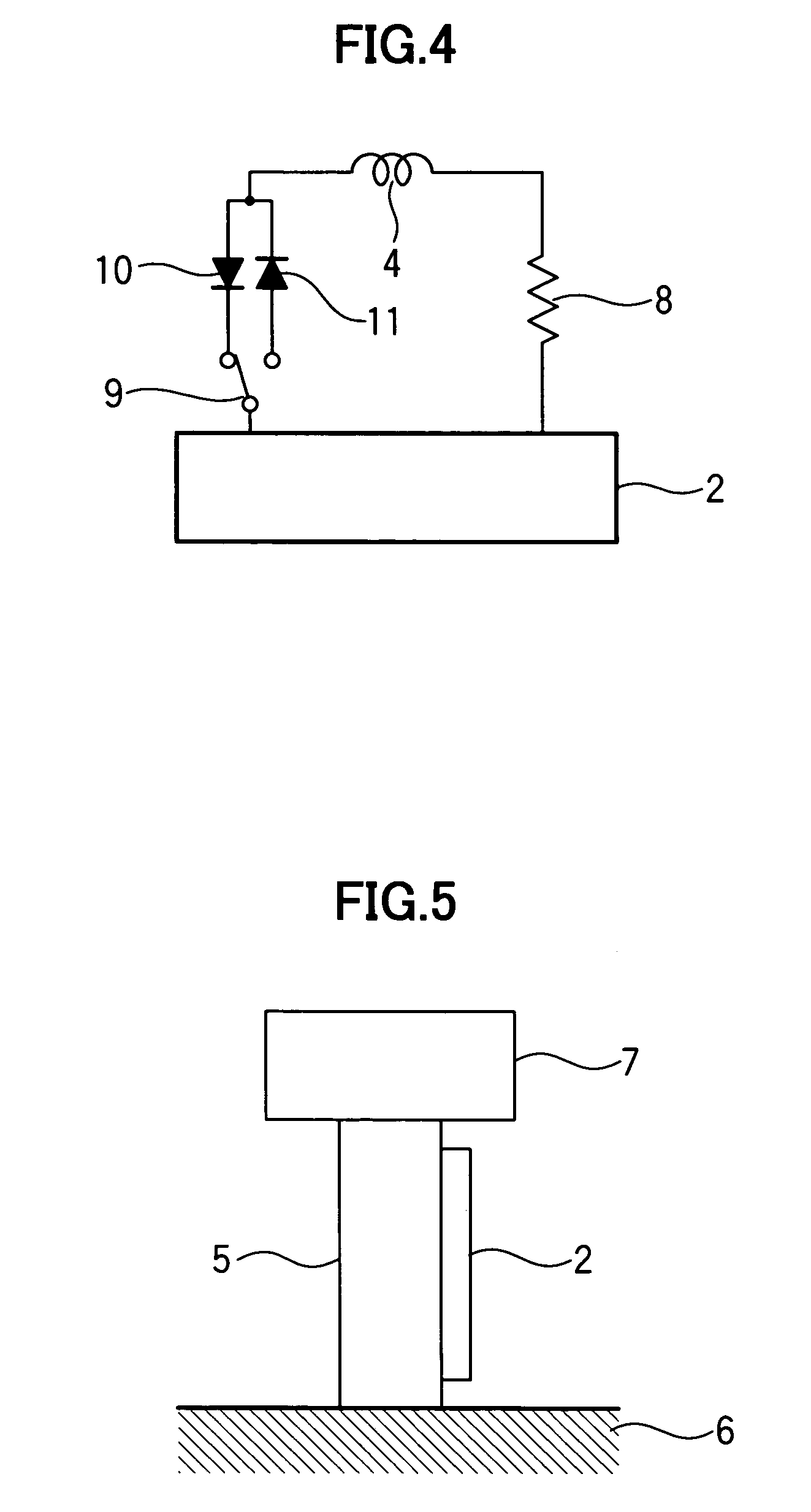
[0051]Referring to FIG. 5, a dead-weight 7 is supported relative to a stationary base 6 through a structure 5. A piezoelectric element 2 is mounted on the structure 5. In conjunction with a displacement of the dead-weight 7, a strain occurs in the piezoelectric element, and a voltage is generated between two electrodes of the piezoelectric element. A circuit illustrated in FIG. 6 is joined to the piezoelectric element 2. In FIG. 6, the piezoelectric element 2 is illustrated as a combination of a capacitor 21, a voltage generator 22 and a resistor 23.

[0052]In this arrangement, a discussion will be firstly made in an initial state when no electric charge is accumulated in the capacitor 21, and the dead-weight 7 is vibrated and moved in a positive direction. As described above, a voltage is generated between the electrodes of the piezoelectric element in conjunction with the movement of the dead-weight 7 in the positive direction. This is equivalent to a state when a positive voltage i...

second embodiment

[0064]As shown in FIG. 8, a plurality of dead-weights each having a weight of 0.5 kg are mounted on a trussed structure having an overall length of 3.8 m and a total mass of about 7.9 kg, and a commercially available piezoelectric element “ASB171C801NPO” (produced by NEC TOKIN Co.) is incorporated in a member 13 of the trussed structure. This trussed structure has a primary natural frequency of about 11.3 Hz. A shunt circuit as shown in FIG. 7 is connected between two electrodes of the above piezoelectric element. Based on the circuit illustrated in FIG. 6, the circuit illustrated in FIG. 7 additionally includes two resisters 85, 86 to prevent the circuit from too sensitively responding to an unwanted voltage variation mixed in a voltage generated by the piezoelectric element due to a higher mode vibration.

[0065]In FIG. 7, each of the coils 41, 42 has an inductance of 10 mH, and each of the capacitors 61, 62 has a capacitance of 0.1 μF. Each of the resistors 81, 83 has a resistance ...

third embodiment

[0068]In the first and second embodiments, two different coils are used for each of the currents flowing across the shunt circuit in the positive direction and in the negative direction. FIG. 10 shows a shunt circuit using a single common coil for both the currents flowing in the positive direction and in the negative direction.

[0069]In FIG. 10, a resistor 23 has a resistance of 1 Ω, and each of two resistances 82, 84 has a resistance of 1 MΩ. Each of two resistances 85, 86 has a resistance of 1 kΩ, and each of two resistances 81, 83 has a resistance of 300 Ω. Each of two coils 46, 47 has an inductance of 0.34 mH, and each of two resistances 87, 88 representing respective resistances of the coils 46, 47 has a resistance of 2 Ω. A capacitor 21 has a capacitance of 10 μF, and each of two capacitors 61, 62 has a capacitance of 0.1 μF. Each of four diodes 51, 52, 53, 56 is based on a numerical modeling equivalent to 6NF11 produced by Toshiba Co., and each of two PUTs 71, 73 is based on ...


PUM


Abstract

Disclosed is a structural vibration damping device, which comprises a piezoelectric element adapted to be mounted on a structure, a shunt circuit inserted between two electrodes of the piezoelectric element, and an electric circuit for selectively opening and closing the shunt circuit. In this damping device, the electric circuit is operable, when a voltage between the electrodes of the piezoelectric element has a positive or negative extreme value due to a vibration of the structure, to close the shunt circuit so as to allow a current to flow between the electrodes of the piezoelectric element, and, when the current is reduced to zero, to open the shunt circuit so as to preclude the current flow until a voltage between the electrodes of the piezoelectric element subsequently has the extreme value. Further, each of the shunt circuit and the electric circuit is designed to be operated using only a power generated by the piezoelectric element. The damping device of the present invention makes it possible to achieve high-performance power-free damping with enhanced reliability and maintainability.

Description

CROSS-REFERENCE TO OTHER APPLICATIONS[0001]The present patent application claims priority from Japanese Patent Application No. 2005-255895, filed on Sep. 5, 2005.BACKGROUND OF THE INVENTION[0002]1. Field of the Invention[0003]The present invention relates to a damping device for damping a vibration of a structure, such as an aerospace structure including a spacecraft and an aircraft, or a transportation structure including an automobile and an electric train.[0004]2. Description of the Related Art[0005]Generally, a vibration occurring in a structure significantly hinders an intended function of the structure, in most situations.[0006]In observation or imaging of a far-off astronomical object with an extremely high spatial resolution in outer space, or in a spacecraft having a mission to take an image of the earth's surface with an extremely high spatial resolution, a vibration in an observational structure, a support structure thereof or a major structure of the spacecraft becomes a...

Claims


Application Information

Patent Timeline
Patent Type & Authority Patents(United States)
IPC IPC(8): H01L41/08F16F15/02H01L41/09
CPCF16F15/005
Inventor ONODA, JUNJIROTAKEUCHI, SHINSUKEYABU, TAKUYA
Owner JAPAN AEROSPACE EXPLORATION AGENCY
Why Eureka
Try Eureka