
Electronic device and method of driving the same

a technology of electronic devices and motors, applied in static indicating devices, electroluminescent light sources, instruments, etc., can solve the problems of limited gray scale, high resolution and multi-gray scale, and the digital gray scale method alone is only capable of displaying in two gray scales

Inactive Publication Date: 2009-07-28
SIPCO
View PDF41 Cites 8 Cited by
  • Summary
  • Abstract
  • Description
  • Claims
  • Application Information

AI Technical Summary

Benefits of technology

This approach enables normal image display and multi-gray scale representation without restricting the length of the sustain period, improving the duty ratio and overall image quality by avoiding address (writing) period overlap.

Problems solved by technology

However, the digital gray scale method by itself is only capable of displaying in two gray scales.
This method has a drawback and there are difficulties in obtaining high resolution and multi-gray scale because the pixel can be divided into only a small number of sub-pixels.
There is no other way than increasing the operation clock to shorten the address (writing) periods and, considering margin for the operation of the circuit, only limited gray scale is possible.
However, the method where an address (writing) period and a sustain (lights-on) period are not separated from each other has the following problem.
Thus there is a limitation in setting the minimum unit for the sustain (lights-on) period when aiming at multi-gray scale.
Since the length of a sustain (lights-on) period is determined by the ratio of power of 2 in the combination of the digital gray scale method and the time gray scale method, obtaining multi-gray scale is difficult within confinement set to the length of one frame period.

Method used


Image

  • Electronic device and method of driving the same
  • Electronic device and method of driving the same
  • Electronic device and method of driving the same

Examples


embodiment 1

[0104]FIG. 20A shows an example of the entire circuit structure. A pixel portion is placed at the center. FIG. 20B is a circuit diagram of one pixel enclosed in a dotted line frame 2000. A source signal line side driver circuit is arranged above the pixel portion. A gate signal line side driver circuit is put to the left of the pixel portion. A storage capacitor line driving circuit is set to the right of the pixel portion.

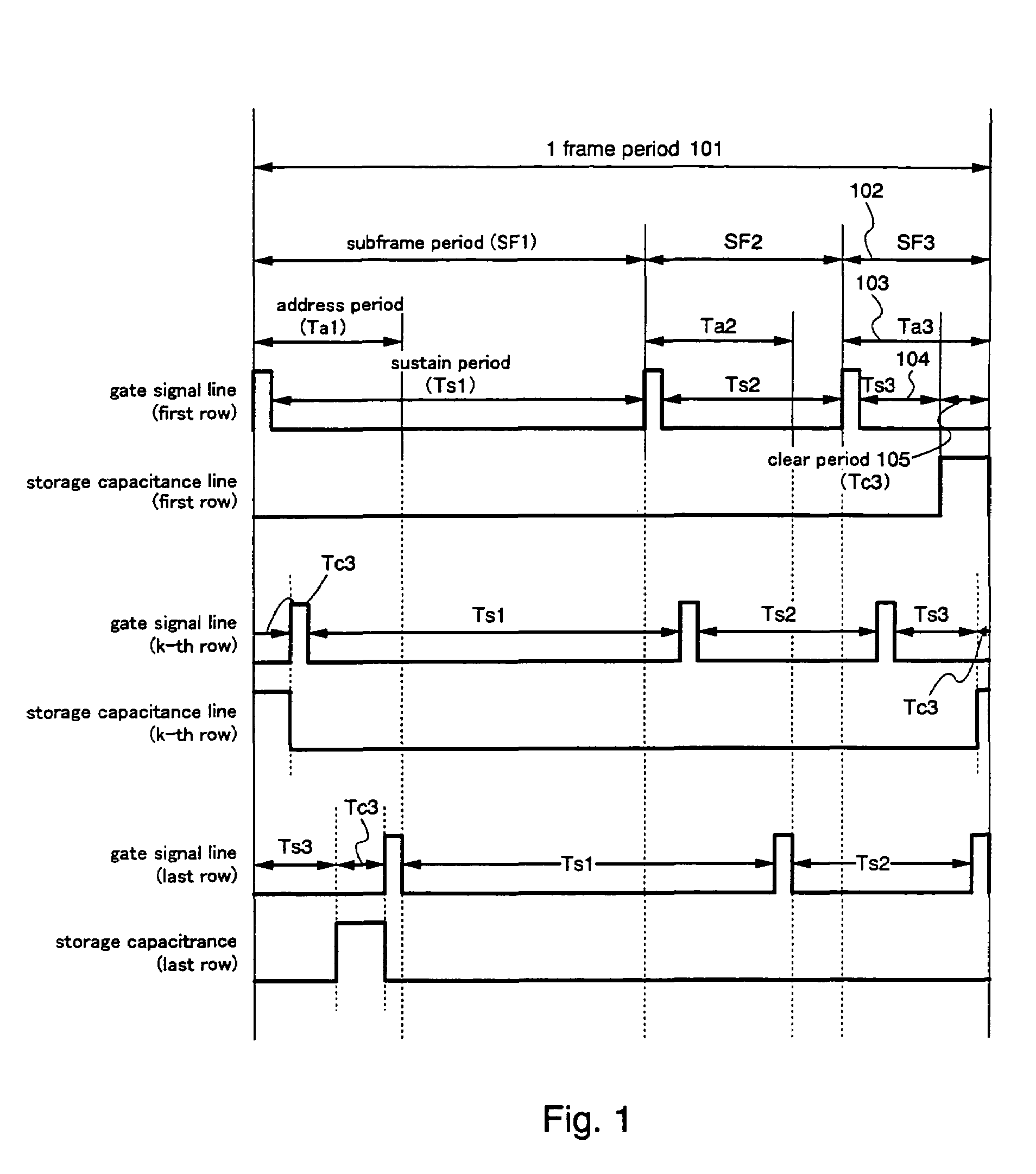
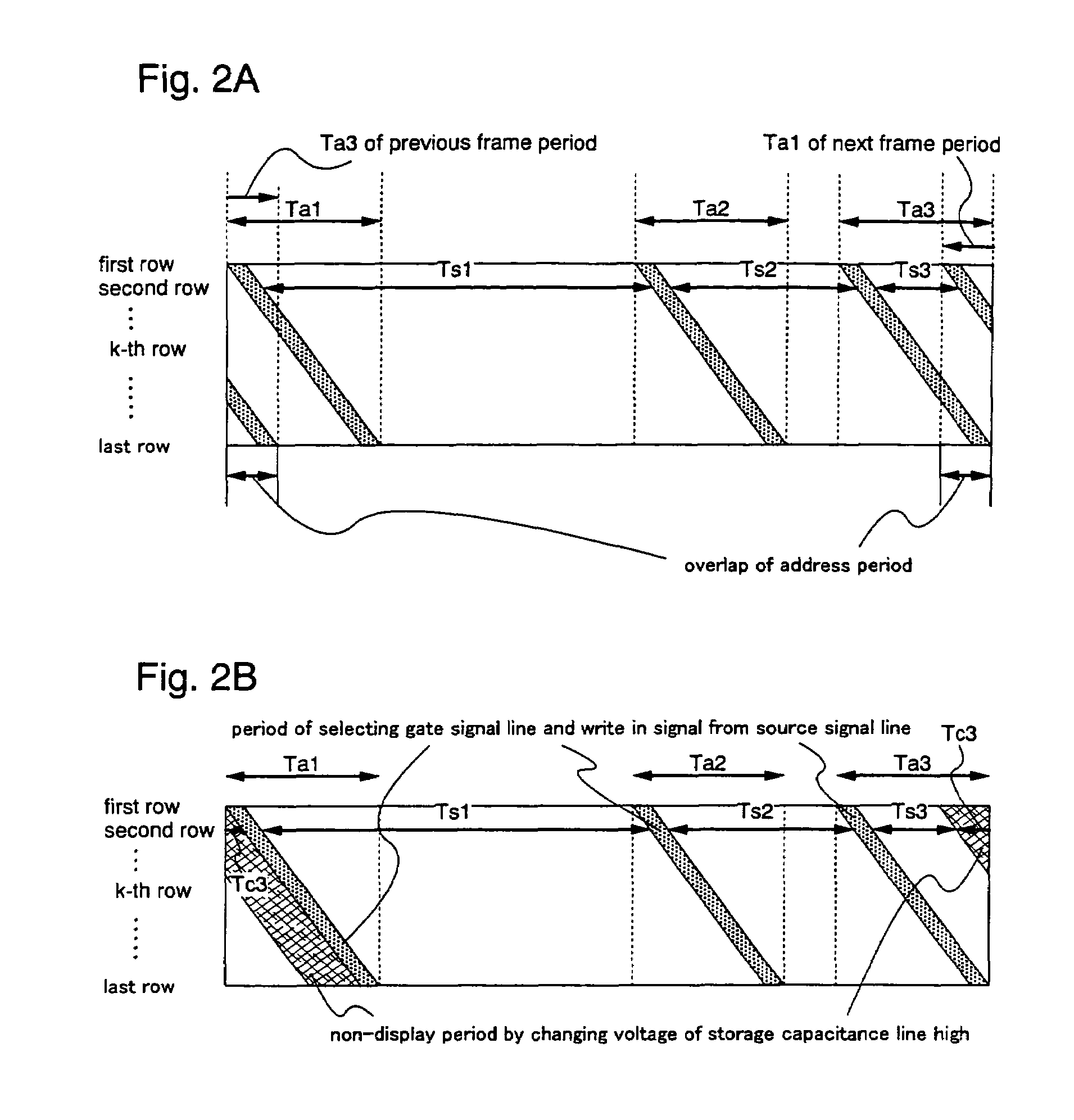
[0105]The actual driving method will be described using a timing chart. Discussed here is a driving method that uses digital gray scale and time gray scale in combination to obtain n bit gray scale display. For simplification, n is set to 3 here and display of 23=8 gray scales will be described. The circuit diagrams of FIGS. 20A and 20B are referred to again.

[0106]FIG. 1 is a timing chart of the electric potential of the gate signal line and of the storage capacitor line in the respective rows in this case. According to the circuit used in this embodiment, a switc...

embodiment 2

[0114]Described in Embodiment 2 is a case in which the number of gray scales is larger than in Embodiment 1, and there are plural sustain (lights-on) periods each of which is shorter than an address (writing) period. The circuit here is the same as the one in Embodiment 1 and reference is again made to FIGS. 20A and 20B.

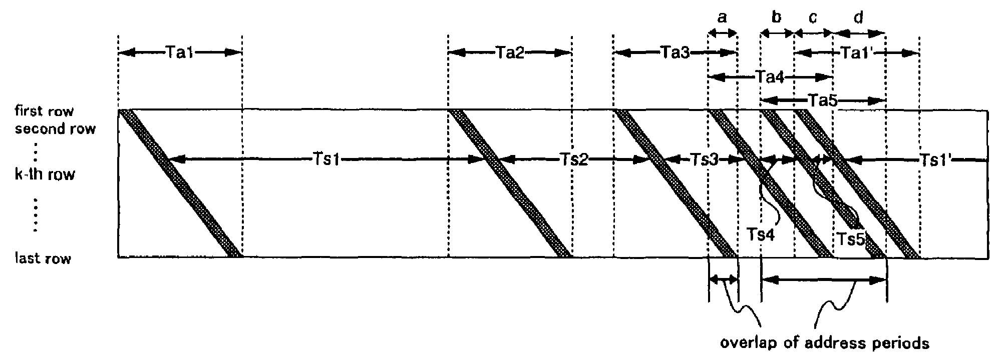
[0115]In this embodiment, display of 5 bit (25=32) gray scales is discussed. Similar to the case of 3 bit gray scale display, address (writing) periods Ta1 to Ta5 all have the same length and sustain (lights-on) periods Ts1 to Ts5 are set so as to satisfy Ts1: Ts2: Ts3: Ts4: Ts5=16:8:4:2: 1. Out of all the sustain (lights-on) periods, Ts3, Ts4 and Ts5 are each shorter than an address (writing) period.

[0116]In a driving method in which the EL element 2003 starts to emit light immediately after writing of signals is completed, if the next address (writing) period is started after the end of a sustain (lights-on) period, address (writing) periods of different sub-frame ...

embodiment 3

[0117]A method of manufacturing TFTs of a driver circuit (n-channel type TFT or p-channel type TFT) provided in the pixel portion and the periphery of a pixel portion on the same substrate is explained in detail in this embodiment.

[0118]First, as shown in FIG. 4A, a base film 5002 made of an insulating film such as a silicon oxide film, a silicon nitride film, or a silicon oxynitride film is formed on a substrate 5001 made from glass, such as barium borosilicate glass or aluminum borosilicate glass, typically Corning Corp. #7059 glass or #1737 glass. For example, a silicon oxynitride film 5002a manufactured from SiH4, NH3, and N2O by plasma CVD is formed with a thickness of 10 to 200 nm (preferably from 50 to 100 nm), and a hydrogenized silicon oxynitride film 5002b with a thickness of 50 to 200 nm (preferably between 100 and 150 nm), manufactured from SiH4 and N2O, is similarly formed and laminated. The base film 5002 with the two layer structure is shown in Embodiment 3, but the b...


PUM


Abstract

To provide a novel driving method for driving an electronic device by using digital gray scale and time gray scale in combination, which secures high duty ratio, which can display an image normally even when a sustain period is shorter than an address period, and which is hardly affected by dulled signal waveform. In a sub-frame period (102) where a sustain period is shorter than an address period, a clear period (105) is squeezed in between completion of a sustain period (104) and start of an address period of the subsequent sub-frame period. The length of the sustain period (104) thus can be set without being limited by the length of an address period (103). This non-display period is provided by changing the electric potential of a storage capacitor line. Therefore, unlike the case where the non-display period is provided by changing the electric potential of a cathode wiring, the present invention is hardly affected by dulled signal waveform.

Description

[0001]This application is a continuation of U.S. application Ser. No. 09 / 836,719 filed On Apr. 17, 2001 now U.S Pat. No 6,847,341.BACKGROUND OF THE INVENTION[0002]1. Field of the Invention[0003]The present invention relates to the structure of an electronic device. The invention particularly relates to a method of driving an active matrix electronic device having a thin film transistor (TFT) that is formed on an insulator and to an electronic device driven by the method.[0004]2. Description of the Related Art[0005]EL displays have lately been attracting attention as a flat panel display to replace LCDs (liquid crystal displays), and researches are being actively made on the EL displays.[0006]Similar to LCDs that have roughly two types of driving methods with one being passive matrix type used in, e.g., STN-LCDs and the other being active matrix type used in, e.g., TFT-LCDs, EL displays also are driven by roughly two types of driving methods. One is passive matrix type and the other ...

Claims


Application Information

Patent Timeline
Patent Type & Authority Patents(United States)
IPC IPC(8): G09G3/30G09G3/20G09G3/32H05B44/00
CPCG09G3/2022G09G3/3258G09G3/2018G09G2300/0426G09G2310/061G09G2300/0861G09G2300/0876G09G2310/0262G09G2300/0842H10K59/8723H10K59/131H10K59/1213H10K59/1216H10K50/8428H10K59/1201G09G3/3266G09G2310/08
Inventor KIMURA, HAJIMETANADA, YOSHIFUMI
Owner SIPCO
Features
  • Generate Ideas
  • Intellectual Property
  • Life Sciences
  • Materials
  • Tech Scout
  • Unparalleled Data Quality
  • Higher Quality Content
  • 60% Fewer Hallucinations
Learn More