
Multiband amplifier based on discrete SOA-Raman amplifiers

a multi-band amplifier and amplifier technology, applied in the field of transporting optical signals, can solve the problems of uncommercialization acceptance of technology, difficult production of amplifiers with low polarization-dependent gain (pdg), and cwdm is presently considered an unamplified technology

Active Publication Date: 2009-07-28
AMERICAN TELEPHONE & TELEGRAPH CO
View PDF12 Cites 0 Cited by
  • Summary
  • Abstract
  • Description
  • Claims
  • Application Information

AI Technical Summary

Benefits of technology

"The present invention provides an amplifier system for amplifying data-bearing optical signals in a bidirectional optical transport system. The system includes a signal separator for separating the optical signal into multiple wavelength bands, each containing a different wavelength division multiplexed channel. A discrete hybrid optical amplifier is connected to each wavelength band, with a semiconductor optical amplifier also connected in series with the discrete amplifier. The amplified wavelength bands are then recombined to form a recombined amplified data-bearing optical signal. The system has improved amplification and signal-to-noise ratios, as well as reduced latency and improved bandwidth."

Problems solved by technology

Although more versatile amplifiers have been demonstrated in the lab, such as semiconductor optical amplifiers (SOA) and Raman amplifiers, those technologies have not gained commercial acceptance due to their inability to compete with the low cost and high performance of EDFAs.
1) Commercial EDFAs can be produced with higher gains and higher output powers than can SOAs.
2) Producing amplifiers with low polarization-dependent gain (PDG) is more challenging for SOAs than for EDFAs.
3) Due to the differences in carrier lifetimes in the two gain media, SOAs are susceptible to inter-channel gain-saturation-induced crosstalk, while EDFAs are largely immune to that adverse effect.
4) SOAs suffer from pronounced gain variations across optical bandwidths typical of WDM systems, while EDFA technology is amenable to the production of multi-stage amplifiers which can incorporate gain-flattening filters and other devices to improve amplifier performance without adversely affecting the amplifier noise figure.
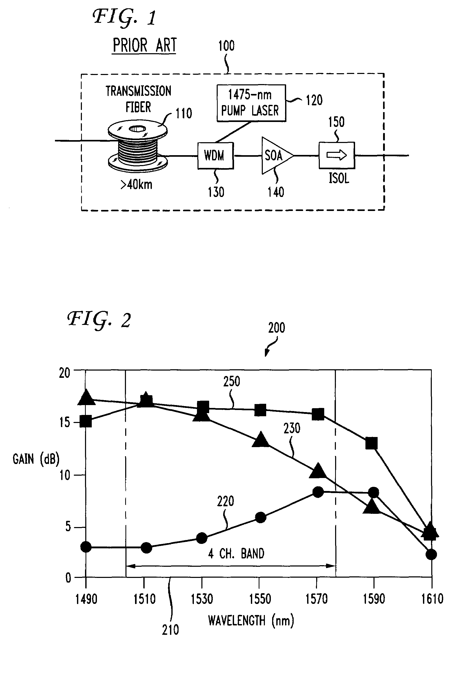
CWDM is presently considered an un-amplified technology due to the unavailability of amplifiers that can operate over the wide optical band of a typical system (1470-1610 nm for an 8-channel system).
Unfortunately, the best of today's commercially available SOAs still exhibit significant gain variations across that operating band, rendering them unsuitable for most practical CWDM (and DWDM) applications.
There have been several recent demonstrations of “discrete” optical amplifiers that display wider optical bandwidth, but at a substantial increase in cost.
Unfortunately, commonly available C-band EDFAs cover less than two CWDM channels, and do not have the versatility to operate over any band within the low-loss window of optical fiber.
That arrangement promises impressive performance with relatively flat gain of 22.5 dB over the conventional 8-channel CWDM band from 1463 nm to 1617 nm, but is complex, has a high component count, and relies on immature technology, all of which contribute to a high cost for this approach.
Diode laser pumps with output powers above 500 mW are not only more costly than lower power pumps, but are considered Class IV lasers and therefore require more stringent (and costly) laser safety procedures of both vendors and network operators.
That design, while simpler than the rare earth doped fiber amplifier mentioned previously, has a lower net gain of approximately 10 dB and is still considered too complex and costly for metro and access applications.
As presently implemented, CWDM must be considered an un-amplified technology since the large wavelength spread occupied by all channels in a typical commercial CWDM system (for example, 153 nm for an 8-channel system) cannot be accommodated by readily available low cost optical amplifiers.
That constraint limits the reach of most existing CWDM systems to about 80 km.

Method used


Image

  • Multiband amplifier based on discrete SOA-Raman amplifiers
  • Multiband amplifier based on discrete SOA-Raman amplifiers
  • Multiband amplifier based on discrete SOA-Raman amplifiers

Examples


Embodiment Construction

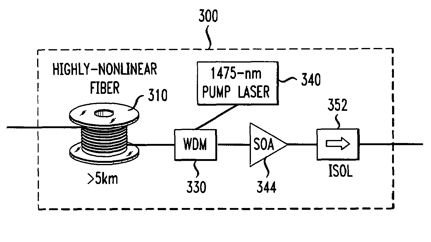
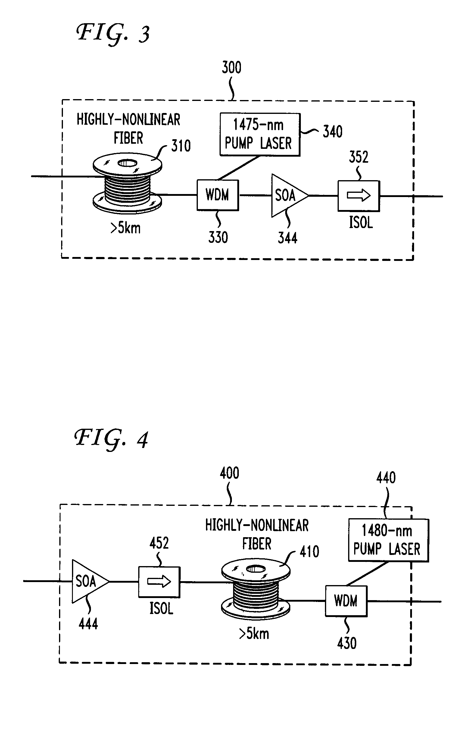
[0043]The inventors have developed a low cost discrete hybrid SOA-Raman amplifier capable of simultaneously amplifying multiple WDM channels over a broad optical band (up to ˜80 nm) with a center wavelength that can be specified (with the proper choice of Raman pump wavelength and SOA) over the entire low-loss band in optical fiber (˜1300-1600 nm). The commercial availability of such an amplifier could open the door to far more flexible and efficient optical networks, particularly in the metro and access portions of the network where flexibility and low cost are paramount.

[0044]A potential drawback of the distributed hybrid amplifier described above is the fact that the Raman gain occurs along the transmission fiber. To that point, service providers have been reluctant to deploy distributed Raman amplifiers for several reasons:

[0045]1) The overall Raman gain is dependent on the type, batch, and manufacturer of the transmission fiber as well as any additional losses or reflections in...


PUM


Abstract

Several discrete hybrid amplifiers are used in parallel for amplifying an optical signal in an optical fiber system. An optical signal is first split into two or more separate signals each with a separate wavelength band. Each wavelength band is then amplified by a Raman pump utilizing a length of highly non-linear fiber as the gain medium, and by an SOA amplifier. The combination of the Raman amplifier and the SOA yields a level gain over the wavelength band. The amplified wavelength band signals are then recombined. The disclosed amplifier is especially useful in coarse wavelength division multiplexing (CWDM) systems and in local access portions of the network.

Description

CLAIM OF PRIORITY[0001]This application is a continuation-in-part of U.S. patent application Ser. No. 11 / 412,645, filed Apr. 27, 2006, now U.S. Pat. No. 7,443,575 and entitled “Discrete Hybrid SOA-Raman Amplifier with Broad Gain Bandwidth,” and claims priority to U.S. Provisional Patent Application Ser. No. 60 / 765,149, filed Feb. 3, 2006, and entitled “Multi-Band Amplifier Based on Discrete SOA-Raman Amplifiers.”FIELD OF THE INVENTION[0002]The present invention relates generally to transporting optical signals on an optical fiber over moderate distances. More particularly, the present application relates to the use of discrete hybrid amplifiers, including a semiconductor optical amplifier and Raman amplifier components, to amplify a signal having a wavelength range larger than the effective range of the individual discrete hybrid amplifiers.BACKGROUND OF THE INVENTION[0003]Although low-loss optical fiber, reliable laser transmitters and low-noise optical receivers have been commerci...

Claims


Application Information

Patent Timeline
Patent Type & Authority Patents(United States)
IPC IPC(8): H01S4/00
CPCH04J14/0221H04B10/2916H01S3/2375H01S3/2383H01S3/302H04B2210/258H04J14/02H01S5/50
Inventor IANNONE, PATRICK P.REICHMANN, KENNETH C.ZHOU, XIANG
Owner AMERICAN TELEPHONE & TELEGRAPH CO
Learn More