System and method for quality assurance of a biosensor test strip

a biosensor and test strip technology, applied in biomass after-treatment, enzymology, biological testing, etc., can solve the problems of physical damage of the test strip, noise added to the measurement, and the diabetic being deprived of using his or her fingers, hands, feet, etc., to achieve the effect of reducing the risk of abrasion, cracking, scratches,

Active Publication Date: 2009-08-04
ROCHE OPERATIONS +1
View PDF860 Cites 47 Cited by
  • Summary
  • Abstract
  • Description
  • Claims
  • Application Information

AI Technical Summary

Problems solved by technology

Failure to do so can produce extreme complications, including blindness and loss of circulation in the extremities, which can ultimately deprive the diabetic of use of his or her fingers, hands, feet, etc.
If this offset varies from test strip to test strip, then noise is added to the measurement result.
Furthermore, physical damage to the test strip 10, such as abrasion, cracks, scratches, chemical degradation, etc. can occur during manufacturing, shipping, storage and / or user mishandling.
These defects can damage the conductive areas 14,16 to the point that they present an extremely high resistance or even an open circuit.

Method used


Image

  • System and method for quality assurance of a biosensor test strip
  • System and method for quality assurance of a biosensor test strip
  • System and method for quality assurance of a biosensor test strip

Examples


first embodiment

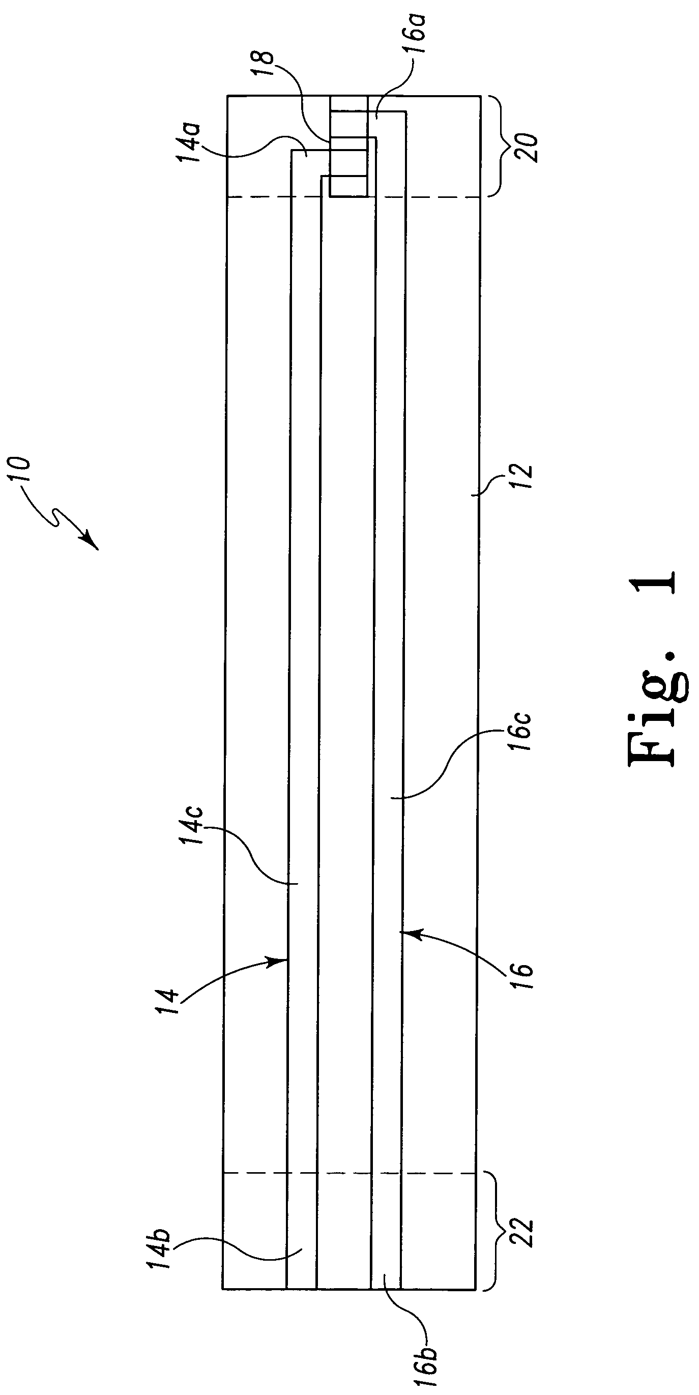
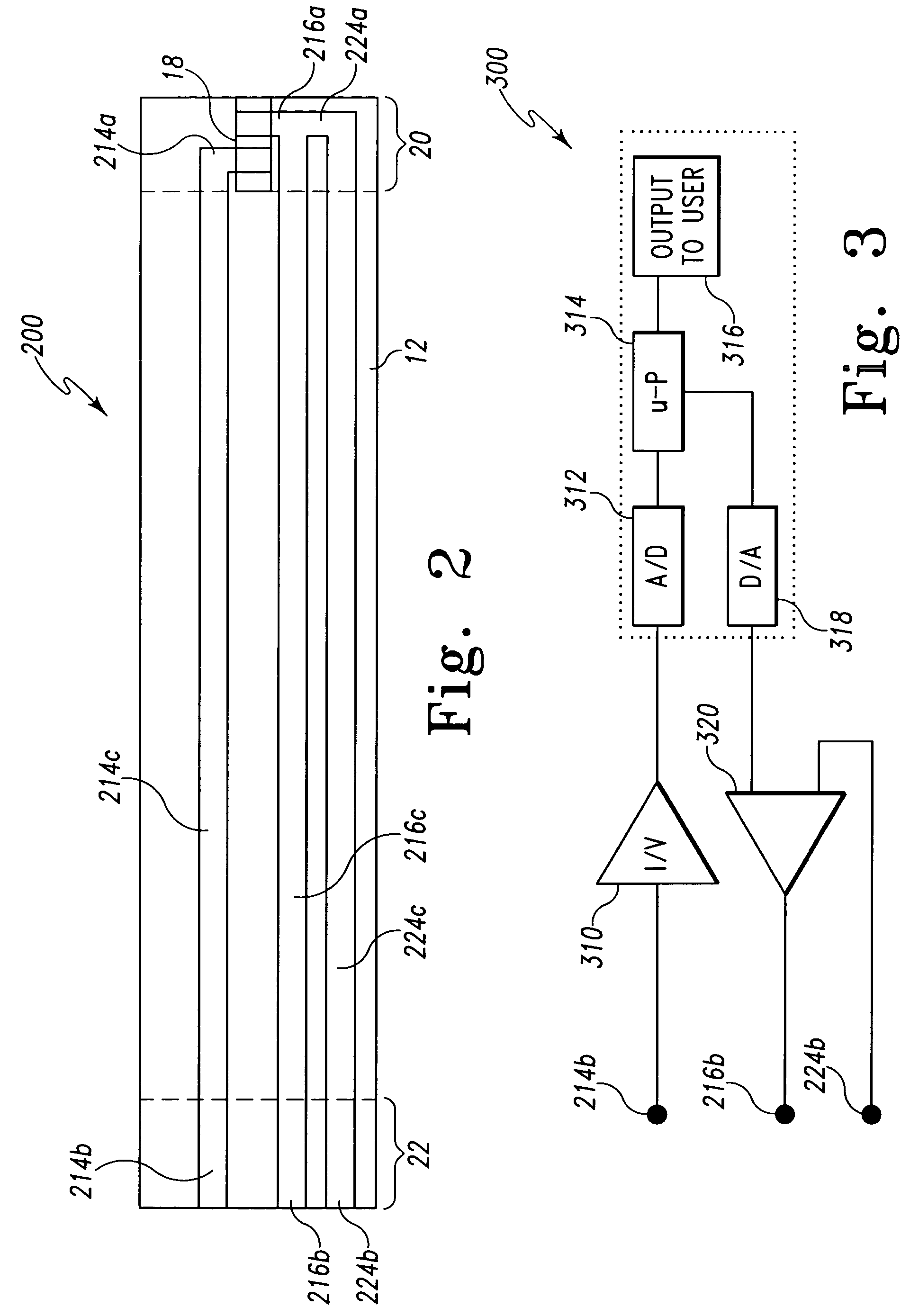
[0024]Although the system and method of the present invention may be used with test strips having a wide variety of designs and made with a wide variety of construction techniques and processes, a first embodiment electrochemical test strip of the present invention is illustrated schematically in FIG. 2, and indicated generally at 200. Portions of test strip 200 which are substantially identical to those of test strip 10 are marked with like reference designators. Referring to FIG. 2, the test strip 200 comprises a bottom substrate 12 formed from an opaque piece of 350 μm thick polyester (such as Melinex 329 available from DuPont) coated on its top surface with a 50 nm conductive gold layer (for instance by sputtering or vapor deposition, by way of non-limiting example). Electrodes, connecting traces and contact pads therefor are then patterned in the conductive layer by a laser ablation process. The laser ablation process is performed by means of an excimer laser which passes throu...

second embodiment

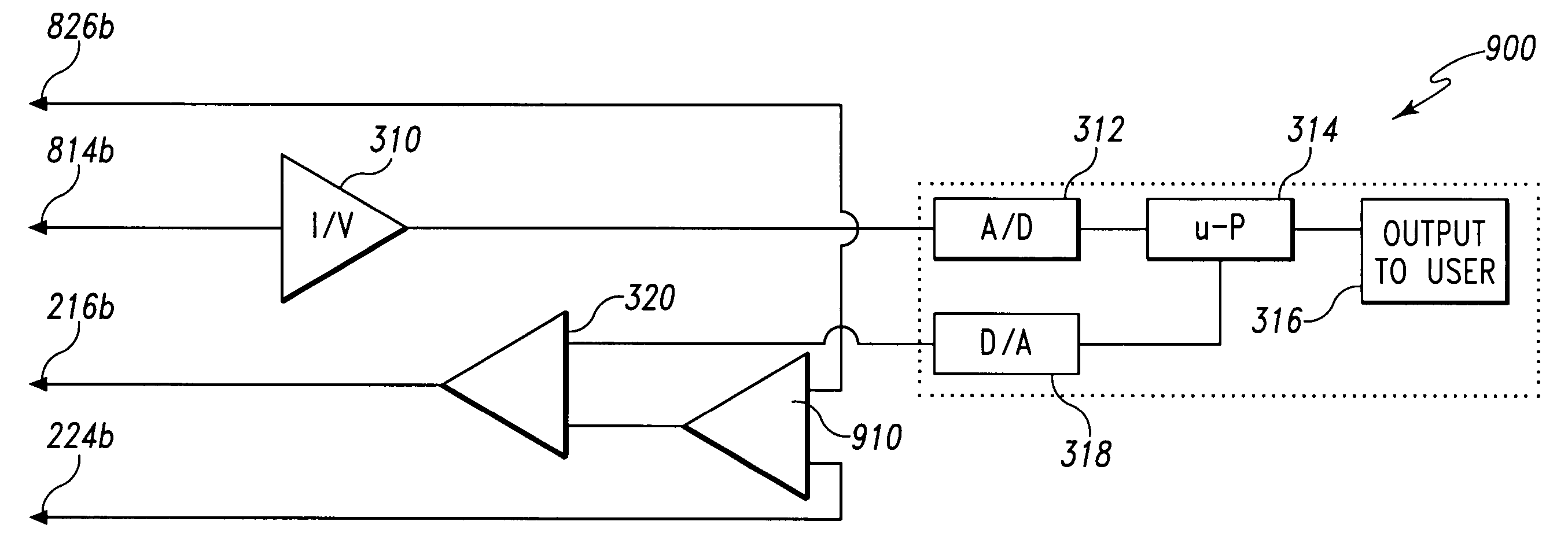
[0047]Referring now to FIG. 9, there is shown a schematic electrical circuit diagram of a second embodiment electrode compensation circuit (indicated generally at 900) housed within the test meter. As indicated, the circuit couples to contact pads 826b, 814b, 216b and 224b when the test strip 800 is inserted into the test meter. As will be appreciated by those skilled in the art, a voltage potential is applied to the counter electrode contact pad 216b, which will produce a current between the counter electrode 216a and the working electrode 814a that is proportional to the amount of analyte present in the biological sample applied to the reagent 18. The current from working electrode 814a is transmitted by working electrode trace 814c to working electrode contact pad 814b and provided to current-to-voltage amplifier 310. The analog output voltage of amplifier 310 is converted to a digital signal by A / D 312. This digital signal is then processed by microprocessor 314 according to a p...


PUM

PropertyMeasurementUnit
thickaaaaaaaaaa
thickaaaaaaaaaa
thicknessaaaaaaaaaa

Abstract

The present invention provides a test strip for measuring a signal of interest in a biological fluid when the test strip is mated to an appropriate test meter, wherein the test strip and the test meter include structures to verify the integrity of the test strip traces, to measure the parasitic resistance of the test strip traces, and to provide compensation in the voltage applied to the test strip to account for parasitic resistive losses in the test strip traces.

Description

REFERENCE TO RELATED APPLICATIONS[0001]This application claims the benefit of U.S. Provisional Application No. 60 / 581,002, filed Jun. 18, 2004. This application is also related to application Ser. No. 10 / 871,937, filed Jun. 18, 2004, and which is incorporated herein by reference in its entirety.TECHNICAL FIELD OF THE INVENTION[0002]The present invention relates to an apparatus for use in measuring signals such as those related to concentrations of an analyte (such as blood glucose) in a biological fluid as well as those related to interferants (such as hematocrit and temperature in the case of blood glucose) to analyte concentration signals. The invention relates more particularly to a system and method for quality assurance of a biosensor test strip.BACKGROUND OF THE INVENTION[0003]Measuring the concentration of substances in biological fluids is an important tool for the diagnosis and treatment of many medical conditions. For example, the measurement of glucose in body fluids, suc...

Claims


Application Information

Patent Timeline
Patent Type & Authority Patents(United States)
IPC IPC(8): G01N27/327G01N27/416G01N33/487
CPCG01N27/3274G01N27/327G01N27/4163G01N27/3273
Inventor CELENTANO, MICHAEL J.GROLL, HENNINGPAULEY, JAMES L.MOORE, STEVEN K.
Owner ROCHE OPERATIONS
Why Eureka
Try Eureka