Monolithic microwave integrated circuit (MMIC) waveguide resonators having a tunable ferroelectric layer

a technology of ferroelectric layer and integrated circuit, which is applied in the direction of resonators, oscillators, electrical equipment, etc., can solve the problems of inability to tun, inability to meet the requirements of high-q resonators, etc., to achieve convenient integration, eliminate losses associated with coupling to external devices, and simplify manufacturing process

Active Publication Date: 2009-08-04
NORTHROP GRUMMAN SYST CORP
View PDF9 Cites 222 Cited by
  • Summary
  • Abstract
  • Description
  • Claims
  • Application Information

AI Technical Summary

Benefits of technology

[0008]The present invention is embodied in a tunable, monolithic, and high-Q waveguide resonator, capable of operation at radio frequencies designated as microwave, millimeter wave and beyond. Briefly, and in general terms, the invention may be defined as a monolithic 3-dimensional resonator, comprising a waveguide defining a resonator cavity formed within a three-dimensional integrated circuit structure; means for electromagnetically coupling the resonator cavity to other components in the integrated circuit structure; a ferroelectric layer formed in the resonator cavity; and means for voltage biasing the ferroelectric layer to effect a desired change in resonator frequency characteristics. Varying the bias voltage applied to the ferroelectric layer changes the dielectric properties of the cavity and, therefore, the resonant frequency. In this way the resonator is electronically tunable.
[0013]Because the resonator may be conveniently integrated with a device with which it is coupled, such as a VCO, losses associated with coupling to external devices are eliminated. Moreover, the integrated nature of the resonator and devices to which it is coupled results in simplification of the manufacturing process. The resonator is frequency tunable by conveniently adjusting a bias voltage applied to the ferroelectric layer, and the entire resonator structure is easily scalable to produce extremely high frequencies, such as millimeter-wave frequencies. Because of the frequency tuning function, the device of the invention is highly suited to applications in which the frequency is switched rapidly for security or other purposes.
[0014]It will be appreciated from the foregoing that the present invention represents a significant advance in the field of microwave / millimeter wave resonators. In particular, the ability of the invention to integrate a resonator with other high frequency components, such as VCOs, affords manufacturing economies. The ability to vary the frequency of operation electronically allows the invention to be used in applications requiring agile frequency switching during operation. Other aspects and advantages of the invention will become apparent from the following more detailed description, taken in conjunction with the accompanying drawings.

Problems solved by technology

Unfortunately, it becomes increasingly difficult to design high-Q resonators as the frequency increases.
At millimeter wave frequencies, for example, there are a number of important applications of resonators, but conventional implementations using dielectric resonators (DR) or coaxial ceramic resonators (CCR) become impractical due to manufacturing limitations.
The first is lack of tunability.
Most existing resonators are not electronically tunable.
Frequency tuning generally involves mechanical tuning of the resonator structures, which is tedious, costly and challenging.
A second disadvantage of conventional resonator approaches is their difficulty of manufacturability and ability to be manufactured repeatably.
The dimensions of resonators become too small to be practical for DRs and CCRs at frequencies above 40 GHz.
These not only introduce parasitic impedance effects, but also greatly reduce the repeatability of the overall circuit's performance and tunability.
Planar resonators inherently have a relatively low Q factor, resulting in poor phase noise for a VCO of which such a resonator is a part, and in compromised insertion loss and rejection for filter applications of the resonators.
Yet another disadvantage of resonators of the prior art is their overall high cost.
Scaling DRs and CCRs down in size for higher frequencies of operation is not only technically difficult, but it leads inherently to higher manufacturing cost.

Method used


Image

  • Monolithic microwave integrated circuit (MMIC) waveguide resonators having a tunable ferroelectric layer
  • Monolithic microwave integrated circuit (MMIC) waveguide resonators having a tunable ferroelectric layer
  • Monolithic microwave integrated circuit (MMIC) waveguide resonators having a tunable ferroelectric layer

Examples


Embodiment Construction

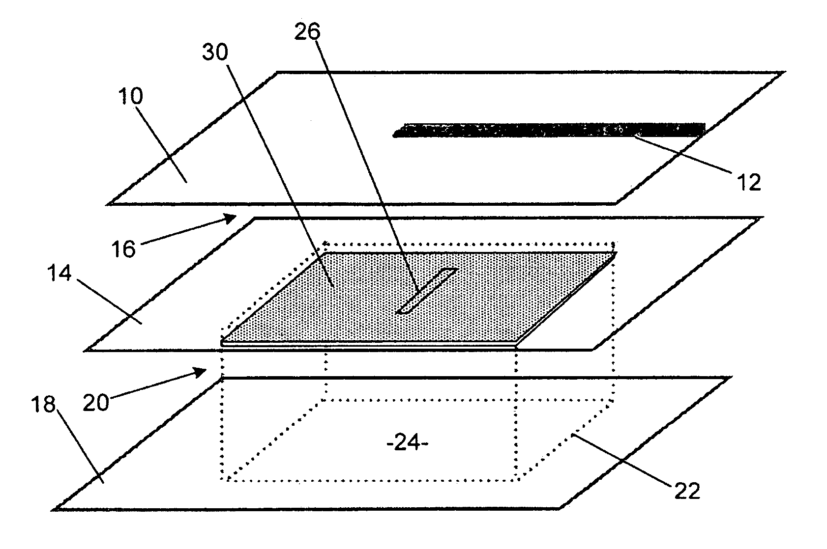
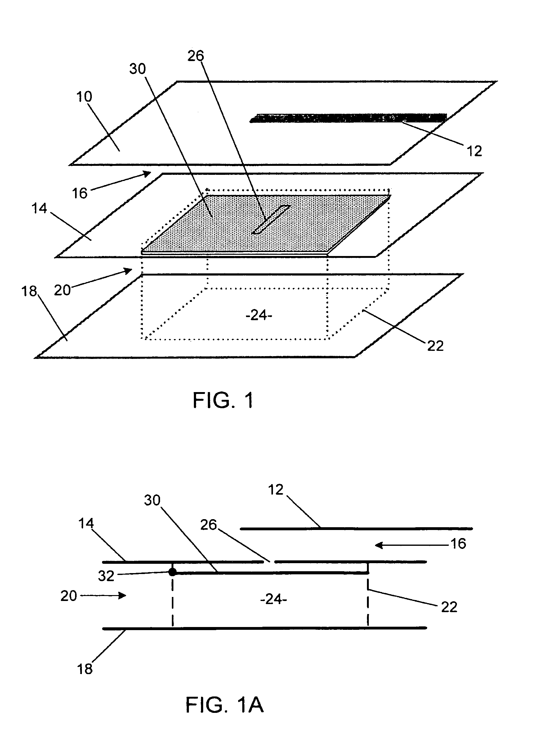
[0020]As shown in the drawings for purposes of illustration, the present invention pertains to radio frequency waveguide resonators. As discussed more fully above, conventional approaches to producing resonators have serious shortcomings when applied to extremely high frequencies. In accordance with the present invention, the disadvantages of the prior art resonators are overcome by providing a high-Q waveguide resonator that is conveniently integrated into a MMIC (monolithic microwave integrated circuit) structure with other related components, is conveniently tunable in resonant frequency, and can be produced reliably and at relatively low cost.

[0021]As shown in FIGS. 1 and 1A, one preferred embodiment of the invention uses a MMIC technique known as multi-layer metal (MLM). The resonator structure depicted includes a first metal layer 10 of FIG. 1 comprising a coupling strip 12 that provides external connection of the resonator to a voltage controlled oscillator (VCO) or other dev...


PUM


Abstract

A ferroelectric loaded waveguide resonator capable of operation at microwave, millimeter-wave and higher frequencies and suitable for integration into a three-dimensional monolithic microwave integrated circuit (3D MMIC) is disclosed. The resonator includes a resonator cavity, which, in one form of the invention, is formed by two parallel metal layers and a metallized wall structure extending between the metal layers. The cavity is filled with dielectric material and includes a layer of ferroelectric material, which is used to control the resonant frequency by varying a voltage bias applied to the ferroelectric layer. The cavity includes a slot in one of the metal layers and a coupling strip formed adjacent to the slot to provide electromagnetic coupling to other components, such as a voltage controlled oscillator (VCO). The invention can also be applied to other multi-metal semiconductor or wafer level packaging technologies.

Description

BACKGROUND OF THE INVENTION[0001]This invention relates generally to 3-dimensional waveguide resonators and, more particularly, to waveguide resonators suitable for applications in the microwave bands and beyond. High-Q resonators are critical components of voltage controlled oscillators (VCOs) and filters, which are widely used in communication systems. There is an ongoing trend in communication systems to utilize higher frequencies. Higher frequencies are not only a less congested area of the radio frequency (RF) spectrum, but also provide technical advantages such as increased bandwidth and increased reliability for military and commercial applications.[0002]A common measure of the performance of a resonator is its quality factor, or Q factor. Basically, the Q factor is a measure of the sharpness of resonance of a resonator. A device with a high Q factor has a sharp, well defined resonance at certain frequency. The Q factor may also be defined as the ratio of the stored energy to...

Claims


Application Information

Patent Timeline
Patent Type & Authority Patents(United States)
IPC IPC(8): H01P7/06
CPCH01P7/065
Inventor KINTIS, MARKFONG, FLAVIA S.WONG, THOMAS T. Y.LAN, XING
Owner NORTHROP GRUMMAN SYST CORP
Why Eureka
Try Eureka