Electric air pump apparatus and evaporation fuel treatment system

a technology of evaporation fuel treatment and air pump, which is applied in the direction of combustion air/fuel air treatment, process and machine control, instruments, etc., can solve the problems of deteriorating mount-properties of the engine room of the vehicle, secondary air supply system, and insufficient negative pressure, so as to improve the control responsiveness of the flow opening valve and reduce the size of the valve drive parts

Inactive Publication Date: 2009-08-18
DENSO CORP
View PDF15 Cites 13 Cited by
  • Summary
  • Abstract
  • Description
  • Claims
  • Application Information

AI Technical Summary

Benefits of technology

[0009]An object of the present invention is to provide an electric air pump and an evaporation fuel treatment system, which can perform downsizing of a valve drive part for opening / closing a flow opening valve. Another object of the present invention is to provide an electric air pump and an evaporation fuel treatment apparatus, which can improve control responsiveness of a flow opening valve.
[0011]Thus, since the flow opening valve can be opened / closed by use of the rotary motion of the electric air pump (for example, motor torque of a motor shaft for rotating and driving a pump impeller), downsizing of the valve drive parts for opening / closing the flow opening valve can be made. In addition, the flow opening valve can start opening / closing movement within a short time after the electric air pump starts to operate, thus improving control responsiveness of the flow opening valve. Further, at least the electric air pump (an air pump and a motor), the motion-direction conversion mechanism and the flow opening valve may be integrally provided inside a housing connected air-tightly to the airflow pipe. In this case, a pump case and a valve case are integrally formed, in a side of which an airflow path (valve chamber) communicated with an air path of the airflow pipe and a pump chamber communicated with the airflow path are provided.

Problems solved by technology

When a secondary air supply system is, however, used in the upland region under low atmospheric pressures, a secondary air supply system described in JP-7-158429A can not provide sufficient negative pressures necessary for operating a diaphragm which drives a valve body of the flow opening valve in the combination valve 203.
This method requires a flow opening valve for preventing leakage of fluid such as evaporation fuel at the time of ceasing the electric air pump, thereby deteriorating mount-properties to an engine room for a vehicle.

Method used


Image

  • Electric air pump apparatus and evaporation fuel treatment system
  • Electric air pump apparatus and evaporation fuel treatment system
  • Electric air pump apparatus and evaporation fuel treatment system

Examples


first embodiment

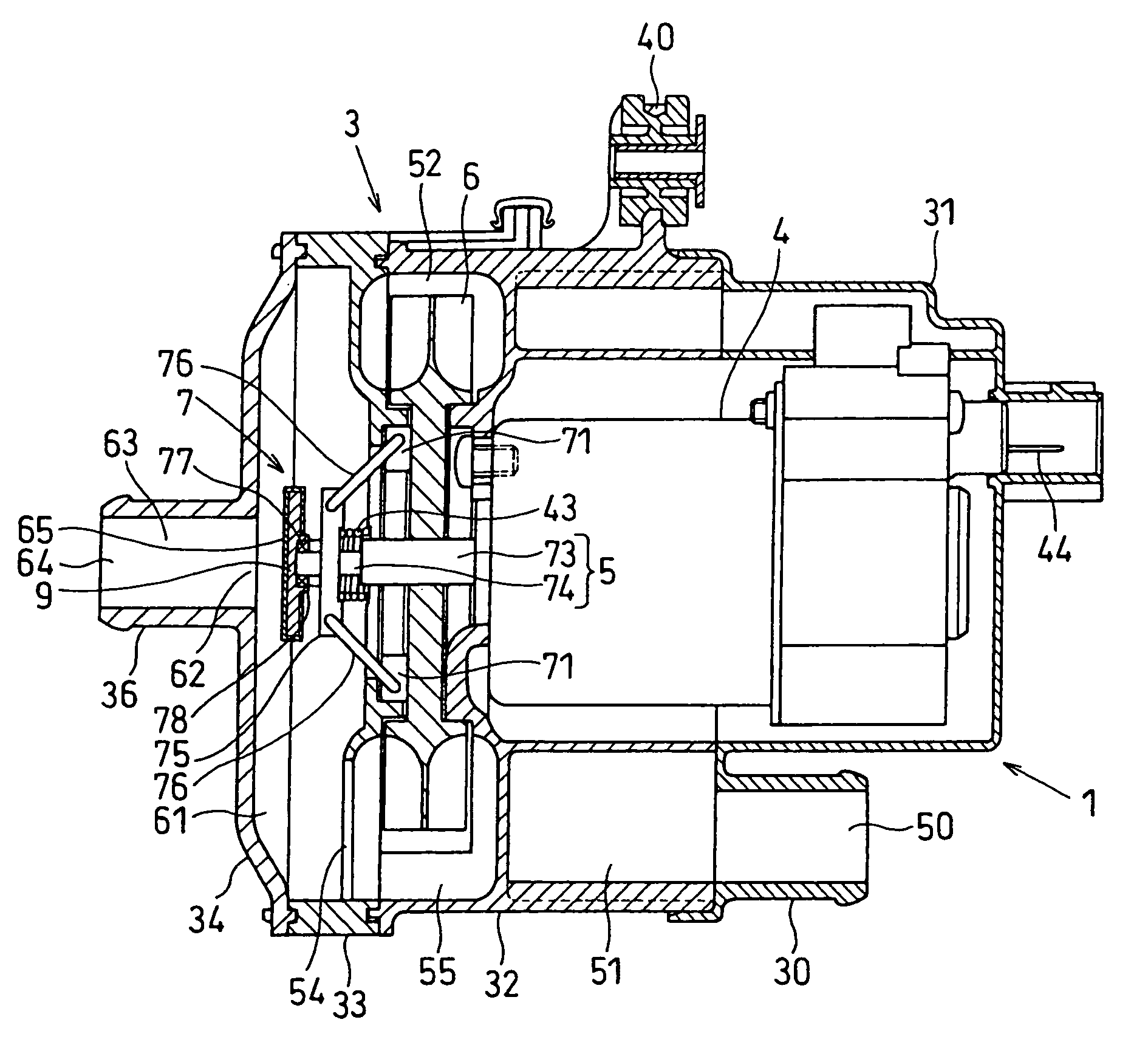
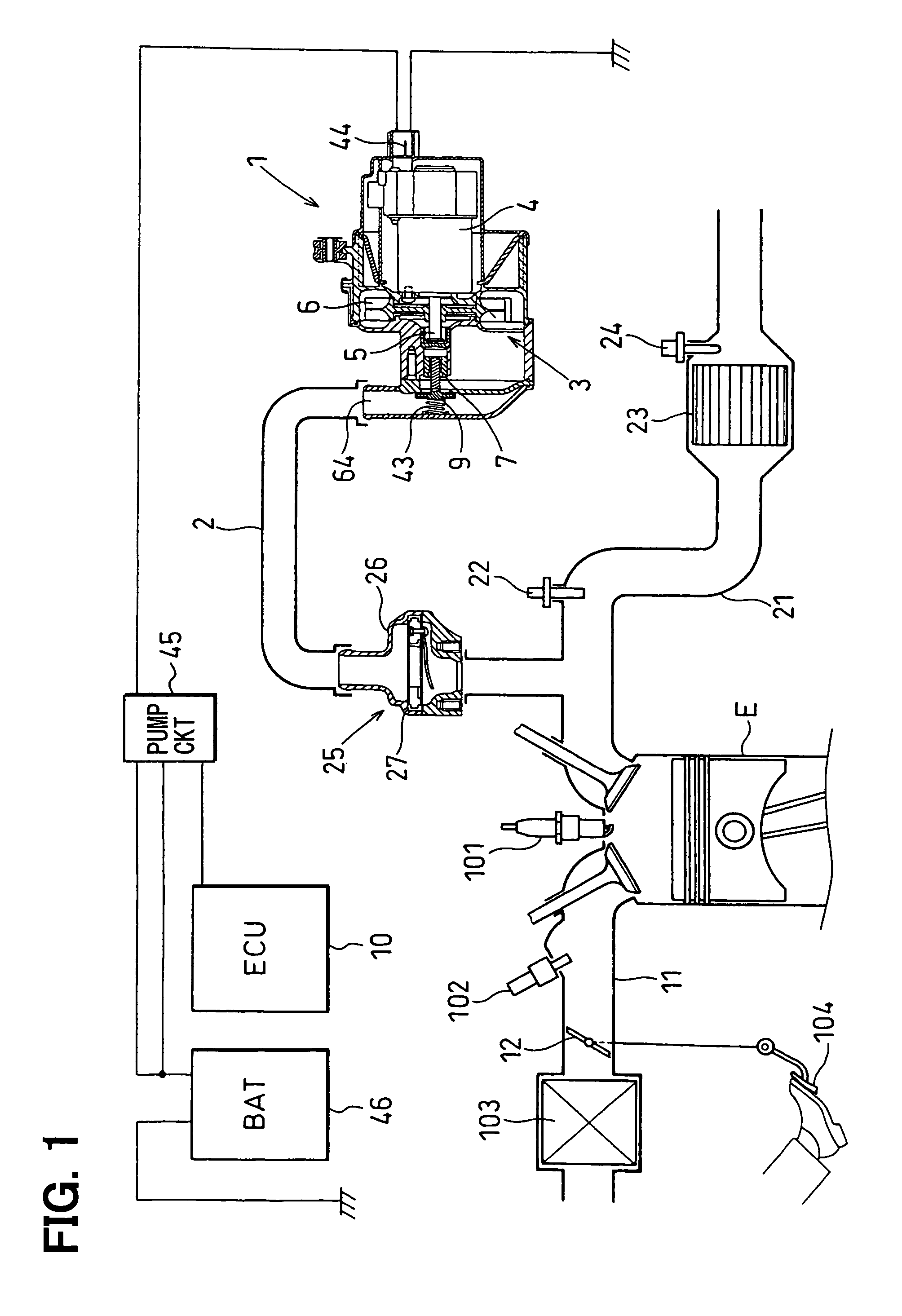
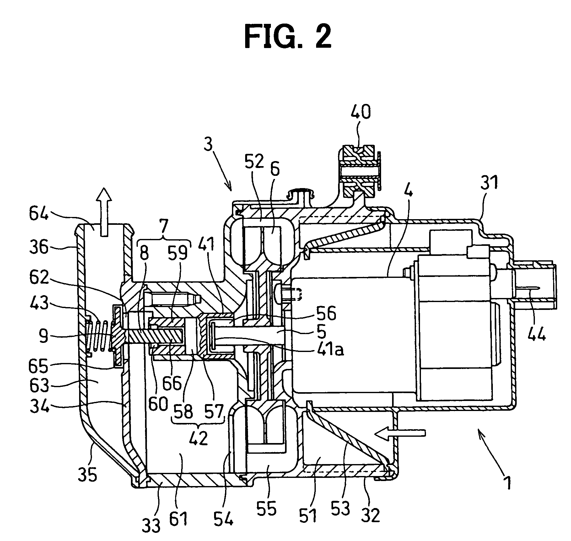
[0041]Referring to FIGS. 1 and 2, a secondary air supply system is mounted in an engine room for a vehicle such as an automobile and is provided with an electric air pump unit 1. The secondary air supply system introduces secondary air generated in a secondary airflow pipe (airflow pipe) 2 at the time of starting an internal combustion engine (engine) E such as a gasoline engine into a three-way catalyst converter 23 to promote warming-up of the three-way catalyst.

[0042]The engine E produces a power output by heat energy obtained by burning a mixture of intake air and fuel in a combustion chamber. The engine E is provided with a cylinder block slidably supporting a piston and a cylinder head including an intake port connected to a downstream end of an engine intake pipe 11 including an intake manifold and an exhaust port connected to an upstream end of an engine exhaust pipe 21 including an exhaust manifold. The intake port and the exhaust port each are opened / closed by an intake va...

second embodiment

[0075]FIGS. 3 and 4 show a second embodiment of the present invention. FIG. 3 is a block diagram showing an entire arrangement of a secondary air supply system. FIG. 4 is a cross section showing an electric air pump unit.

[0076]In the second embodiment, the friction plate 57 of the torque limiter 42 instead of the clutch inner of the centrifugal clutch 41 is mounted integrally with the front end of the motor shaft 5 in the axial direction by joint means such as welding. This causes elimination of the plurality of the clutch weights 56, the clutch inner, the clutch outer and the like, leading to further reduction in the number of components and in assembly labors as compared to the first embodiment. The centrifugal clutch 41 may be provided between the motor shaft 5 and the torque limiter 42. The coil spring 43 may be provided or not provided. In the electric motor 4 of the second embodiment, flow directions of a pump drive current supplied to the armature winding are set as two direc...

third embodiment

[0080]FIGS. 5 and 6 show a third embodiment of the present invention. FIG. 5 is a cross section showing an electric air pump unit.

[0081]In the third embodiment, a stopper 67 is provided in the second valve seat of the fifth case 35. The valve 9 gets in contact with the stopper 67 when the valve 9 opens. In the electric motor 4 in the third embodiment, the rotational directions of the motor shaft 5 are set as two directions which are forward and reverse directions in the same way as in the second embodiment. As a result, the valve 9 can be driven and closed without provision of the coil spring 43, thereby further reduction in the number of components and in assembly labors as compared to the first embodiment. The ECU 10 in the third embodiment includes a known microcomputer therein in the same as in the first embodiment. When the ignition switch is ON and the engine E starts to operate, the ECU 10 adjusts electric power supplied to the electric motor 4 based upon control programs sto...


PUM


Abstract

A self-opened type valve is opened by motor torque of an electric motor. Therefore, a diaphragm is not necessary for opening the valve, and downsizing of a valve drive apparatus for opening the valve is possible. Since the valve is assembled to the motor shaft of the electric air pump via a motion-direction conversion mechanism, an opening action of the valve can start in a short time after a rotational action of the impeller of the electric air pump starts, so that control responsiveness is improved. At a rotation stop of the impeller of the electric air pump, the valve can be maintained in a fully closed condition by an urging force of the coil spring, thereby preventing exhaust gases or condensed water from entering into an inside of the electric air pump.

Description

CROSS-REFERENCE TO RELATED APPLICATION[0001]This application is based on Japanese Patent Application No. 2005-106488 filed on Apr. 1, 2005, the disclosure of which is incorporated herein by reference.FIELD OF THE INVENTION[0002]The present invention relates to an electric air pump apparatus formed of a pump unit equipped with at least an electric air pump and a self-opened air switching valve including a movement direction-changing mechanism and a flow path opening valve. In particular the present invention relates to an electric air pump apparatus incorporated in a secondary air supply system or an evaporation fuel treatment system.BACKGROUND OF THE INVENTION[0003]FIG. 25A shows a known secondary air supply system. This secondary air supply apparatus is designed to activate a three-way catalyst by introducing secondary air generated by operating an electric air pump 201 at the time of starting an internal combustion engine into a three-way catalyst converter (not shown) via a secon...

Claims


Application Information

Patent Timeline
Patent Type & Authority Patents(United States)
IPC IPC(8): F03B15/08
CPCF01N3/22F01N3/225F01N3/32F01N3/323F02M25/0836F01N3/36Y02T10/20F01N2610/08F02M53/02Y02T10/12Y10T137/1135Y02A50/20
Inventor UCHIDA, AKIKAZUNAKAMURA, HIROSHITSUZUKI, KUNIHIROYOKOYAMA, SHINICHIKOBAYASHI, YASUNORI
Owner DENSO CORP
Why Eureka
Try Eureka