
Pulse modulation type electric power amplifier

a technology of electric power amplifier and pulse modulator, which is applied in the direction of single-ended push-pull amplifier, emergency protective circuit arrangement, gain control, etc., can solve the problems of affecting the user's comfort, etc., to achieve low power consumption, small circuitry, and small size

Inactive Publication Date: 2009-09-08
PANASONIC CORP
View PDF9 Cites 5 Cited by
  • Summary
  • Abstract
  • Description
  • Claims
  • Application Information

AI Technical Summary

Benefits of technology

[0014]An object of the present invention is to provide a pulse modulation type electric power amplifier having an output short-circuit protection circuit that can be configured simply with little circuitry, and is therefore small in area, low power consumption and easily integrated.
[0015]A further object of the present invention is to provide a pulse modulation type electric power amplifier having a protection circuit capable of realizing output control and protection in a short time period from clock stoppage.
[0017]According to a pulse modulation type electric power amplifier having this configuration, it is possible to provide protection in the event of an output short circuit with a digital circuit that easily can be embedded in a semiconductor apparatus, without requiring complicated analog circuitry or mutual inductance for measuring voltage or current. Also, since current does not flow constantly, it is possible to realize a low power consumption.
[0019]According to a pulse modulation type electric power amplifier having this configuration, physical harm to the user as well as failure of speakers or headphones connected to the output terminal or failure of the pulse modulation type electric power amplifier itself can be prevented even if clock stoppage occurs. The clock detection circuit can be configured simply with little circuitry, and is therefore small size, low power consumption, and easily integrated. Further, it is possible to realize output control and protection in a short timeframe from clock stoppage because of the feed forward control from the clock.

Problems solved by technology

Also, with pulse modulation type electric power amplifiers, electromagnetic interference (EMI) or physical impacts may cause problems with the clock generating means or with the connection from the clock generating means to the pulse modulator, causing stoppage of the clock signal input to the pulse modulator.
This direct current can cause the load to heat up and thereby physically harm the user as a result of surpassing the allowable current of the load, or cause speakers or headphones connected to the output terminal or the pulse modulation type electric power amplifier itself to fail.
Consequently, a drawback is the complexity and high power consumption of the circuitry.
Another problem is the time taken from when a short circuit is determined until output control is implemented because of the control being performed after feeding back the signal of the output terminal.
Further, with a configuration such as that described in JP H5-160649A, difficulties are encountered in embedding the circuit into a semiconductor apparatus due to the use of mutual inductance, with problems of increased mounting area and power loss caused by the mutual inductance.

Method used


Image

  • Pulse modulation type electric power amplifier
  • Pulse modulation type electric power amplifier
  • Pulse modulation type electric power amplifier

Examples


first embodiment

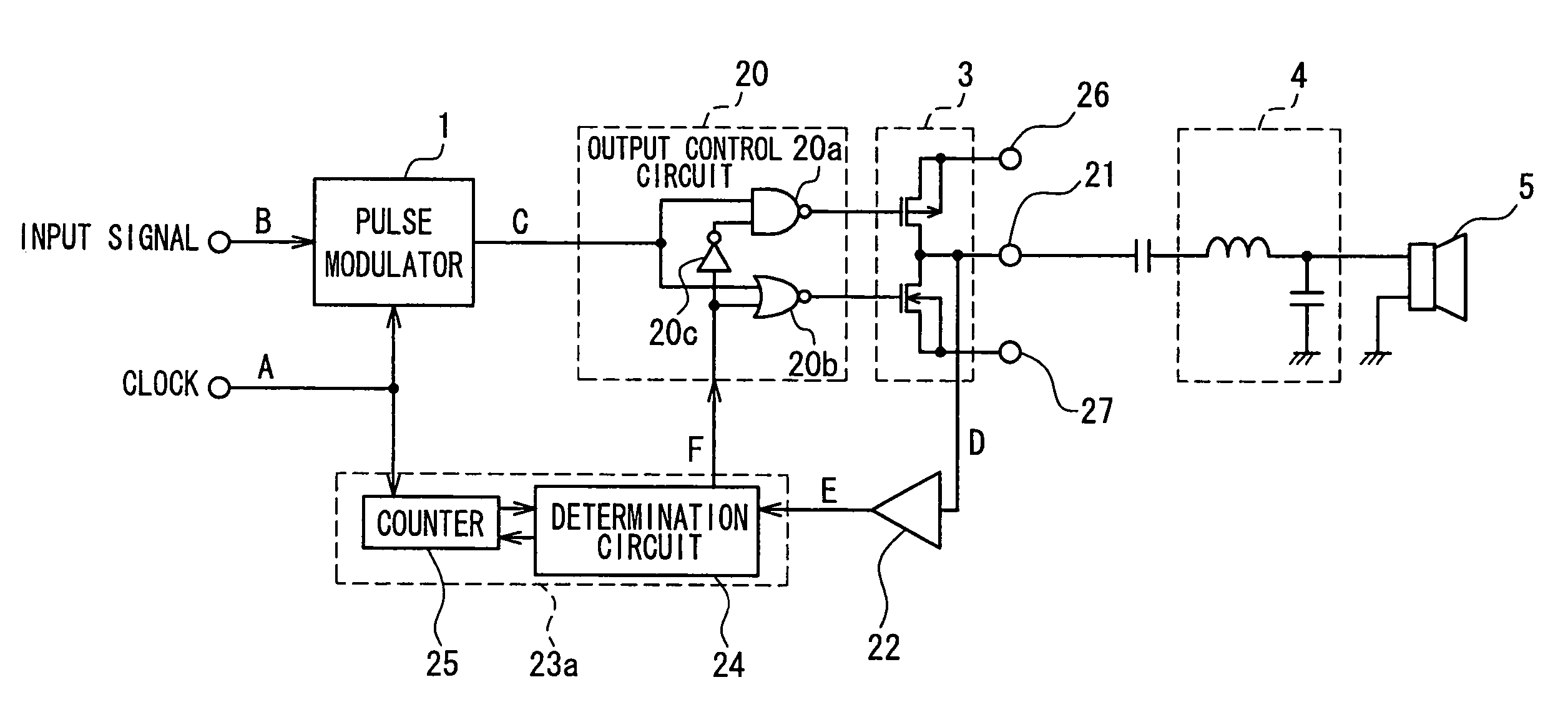
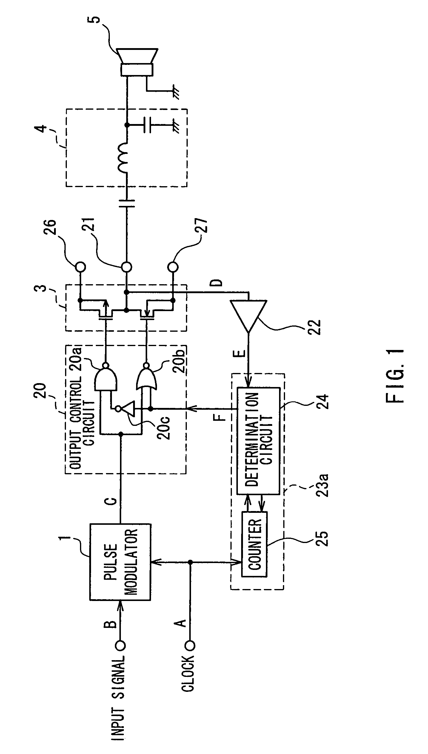
[0051]FIG. 1 is a block diagram showing a pulse modulation type electric power amplifier according to a first embodiment of the present invention. The basic configuration of this circuit is similar to that shown in FIG. 14. The same reference numeral will be attached to like elements, and redundant description will be partly omitted.

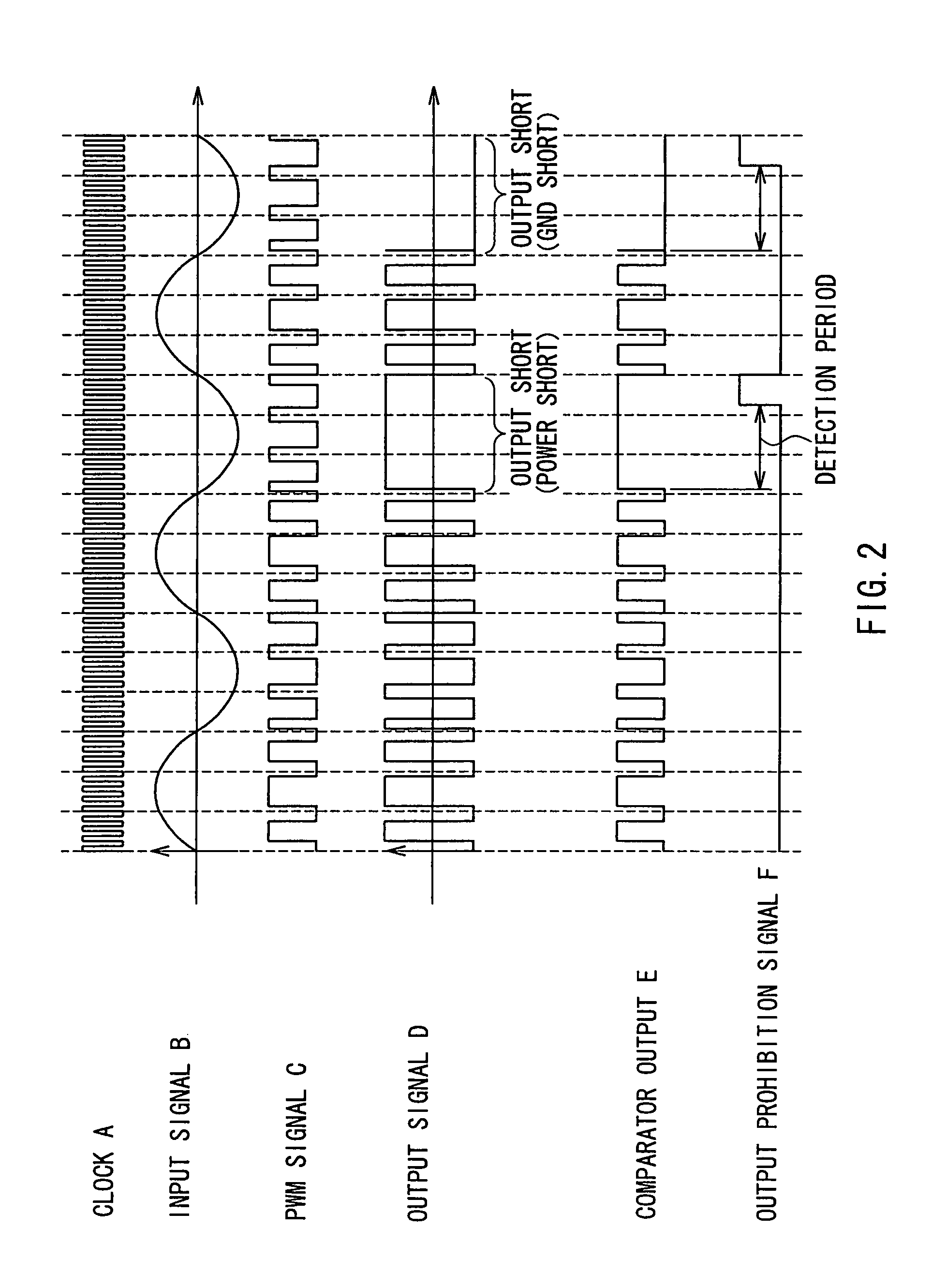
[0052]This pulse modulation type electric power amplifier is basically constituted of a pulse modulator 1 that receives as input a clock A and an analog input signal B, an output control circuit 20 that receives as input an output signal C of the pulse modulator 1 and is configured to be able to stop a switching operation, and an output circuit 3 that performs switching according to the output of the output control circuit 20. Further, a comparator 22 that is connected to an output terminal 21 of the output circuit 3 and a short-circuit determination circuit 23a that is fed with the output of the comparator 22 are provided to constitute protection circui...

second embodiment

[0060]FIG. 3 is a block diagram showing a pulse modulation type electric power amplifier according to a second embodiment of the present invention. This circuit has a configuration in which a short-circuit determination circuit 23b is provided in place of the short-circuit determination circuit 23a in FIG. 1. The short-circuit determination circuit 23b has an EXOR gate 28, with the output E of the comparator 22 being fed as one of the inputs of the EXOR gate 28. The PWM output signal C output from the pulse modulator 1 is fed as the other input of the EXOR gate 28. An output signal G of the EXOR gate 28 is input to the determination circuit 24.

[0061]The operation of this pulse modulation type electric power amplifier is shown in FIG. 4. A to G are the waveforms of the corresponding signals in FIG. 3. The basic operation is similar to the operation of the circuitry in FIG. 1 described with reference to FIG. 2. A difference lies in the operation of the short-circuit determination circ...

third embodiment

[0064]FIG. 5 is a block diagram showing a pulse modulation type electric power amplifier according to a third embodiment of the present invention. The present embodiment relates to a configuration for detecting short circuits between the output terminals of a bridged transformerless (BTL) pulse modulation type electric power amplifier.

[0065]With the circuit in FIG. 5, the output circuit 3 is composed of a first and a second output circuit 3a and 3b having a bridge configuration. PMOS transistor and NMOS transistor pairs of the first and second output circuits 3a and 3b are connected between the power supply terminal 26 and the ground terminal 27, and the connection points of the pairs respectively are connected to a first and a second output terminal 21a and 21b. The output of the first output circuit 3a is differential to the output of the second output circuit 3b.

[0066]An output control circuit 29 has a configuration in which a first and a second output control circuit 29a and 29...


PUM


Abstract

A pulse modulation type electric power amplifier includes a pulse modulator that receives as input a clock and an input signal, and converts the input signal to a pulse train, an output control circuit that receives as input the pulse train output by the pulse modulator, and controls output of the pulse train, an output circuit that performs switching according to the pulse train output by the output control circuit, a comparator that converts an output terminal voltage of the output circuit to a high or a low digital value, and a short-circuit determination circuit that determines whether an output short circuit has occurred based on a state of an output signal of the comparator, and outputs an output prohibition signal to the output control circuit when an output short circuit is detected. The output control circuit controls output of the pulse train when the output prohibition signal is input, so that the output circuit stops the switching operation. An output short-circuit protection circuit can thereby be configured simply with little circuitry, and is thus small, low power, and integrated easily.

Description

BACKGROUND OF THE INVENTION[0001]1. Field of the Invention[0002]The present invention relates to realizing protection when the output terminal of a class D audio amplifier short circuits and to preventing failures in the event of clock stoppage with respect to a pulse modulation type electric power amplifier.[0003]2. Description of the Related Art[0004]Class D audio amplifiers that use pulse width modulation (PWM) or delta-sigma modulation have been utilized in recent years. Pulse modulation power amplifiers such as class D amplifiers are energy efficient in comparison to class A or B amplifiers that amplify analog signals, and have been implemented actively in practical applications.[0005]FIG. 14 shows a block diagram of a common pulse modulation type electric power amplifier. This pulse modulation type electric power amplifier basically is constituted of a pulse modulator 1 that receives as input a clock A and an analog input signal B, and an output circuit 3 that performs switchi...

Claims


Application Information

Patent Timeline
Patent Type & Authority Patents(United States)
IPC IPC(8): H03F3/38
CPCH03F1/52H03F3/2173H03F3/217
Inventor KOBAYASHI, HITOSHIOKAMOTO, KENJI
Owner PANASONIC CORP
Learn More