Modular insert and jack including moveable reactance section

a reactance section and module insert technology, applied in the field of communication connectors, can solve the problems of interference in the cable, and noise being a primary limit factor in the performance of a communication system,

Active Publication Date: 2009-10-13
ORTRONICS INC
View PDF61 Cites 83 Cited by
  • Summary
  • Abstract
  • Description
  • Claims
  • Application Information

AI Technical Summary

Benefits of technology

[0044]In the jack assembly, in response to a mating plug being received in the plug receiving space of the jack housing, the insert device may be operable to move the reactance circuit relative to the at least one plug interface contact at least in part by causing the reactance circuit to rotate vertically upwardly and rearward in response to the at least one plug interface contact rotating vertically downward.

Problems solved by technology

In addition, the use of UTP media, as opposed to STP media, eliminates the possibility of ground loops (i.e., current flowing in the shield because the ground voltage at each end of the cable is not exactly the same, thereby potentially inducing interference into the cable that the shield was intended to protect).
Such distortions and unwanted signals affect the original signal between transmission and reception and are commonly collectively referred to as “electrical noise” or simply “noise.” Noise can be a primary limiting factor in the performance of a communication system.
Indeed, many problems may arise from the existence and / or introduction of noise during data transmission, such as data errors, system malfunctions and loss of the original signals (in whole or in part).
The transmission of data by itself causes unwanted noise.
Thus, there exists an opportunity for significant crosstalk interference.
NEXT increases the additive noise at the receiver and therefore degrades the signal to noise ratio (SNR).
NEXT may be the most significant impediment to effective data transfer because the high-energy signal from an adjacent line can induce relatively significant crosstalk into the primary signal.
Another major source of distortion for high speed signal transmission may be mismatch of transmission impedances.
Thus, signal reflections can lead to an undesirable increase data loss.
As the speeds have increased, so has the noise.
By design, this connector reduces noise but at the expense of excessive pin lengths that can increase or enhance unwanted noises.
Another potential issue with respect to the connector of the Caveney '957 patent could be the insertion of an FCC regulated RJ11 plug insertion into the plug / pin interface.
Because of the deep depression of force that is applied to the outer pins, potential damage could occur to the flexible circuit board, potentially rendering the connector virtually unusable.
This method could be effective at reducing crosstalk, but potentially at a substantial cost (e.g., due to the usage and size of the flexible circuit board).
Although the connector of the Caveney '261 patent has the potential to reduce crosstalk, the methods disclosed could potentially increase fabrication costs and introduce mechanical complication.
The usage of an electrical connection to a stationary printed circuit board further places the compensation at a distance that is further away from origination noise source, thus increasing the chances of allowing additional unwanted noise to be injected into adjacent pairs.
The additional coupling of the connector assembly of the Troutman '371 patent may be inadequate in reducing crosstalk to a required degree because, inter alia, the elongated plates are crossed / overlapped and also adjacent, thus creating unwanted parallelisms between contacts 3 to 4 and contacts 5 to 6 and undesirably increasing crosstalk noises.
Although crosstalk noise may be reduced by the design of the connector assembly of the Troutman '371 patent, the effective complex modes of coupling may be more than doubled, which potentially increases NEXT, FEXT and noise variation factors.
Of note, a design of the type disclosed in the Arnett '742 patent can undesirably decrease contact flexibility, thereby adds complexity to design efforts.
In addition, utilizing a curved spring beam contact design can increase unwanted NEXT / FEXT noises because of the adjacencies between pairs.

Method used


Image

  • Modular insert and jack including moveable reactance section
  • Modular insert and jack including moveable reactance section
  • Modular insert and jack including moveable reactance section

Examples


Embodiment Construction

)

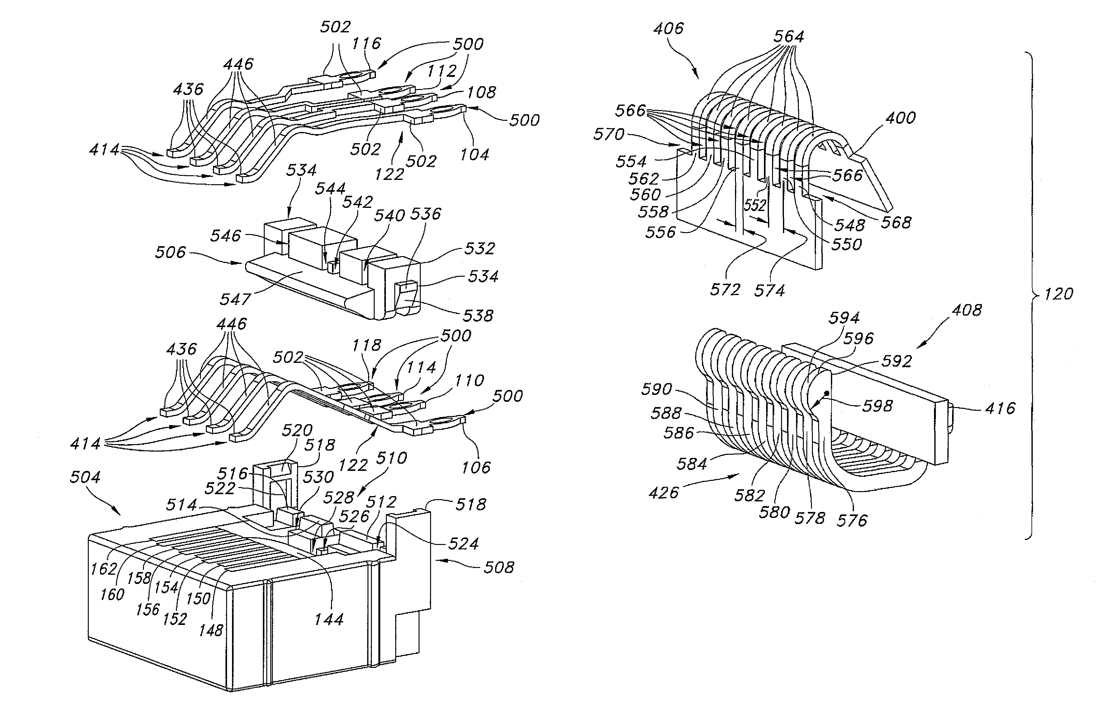
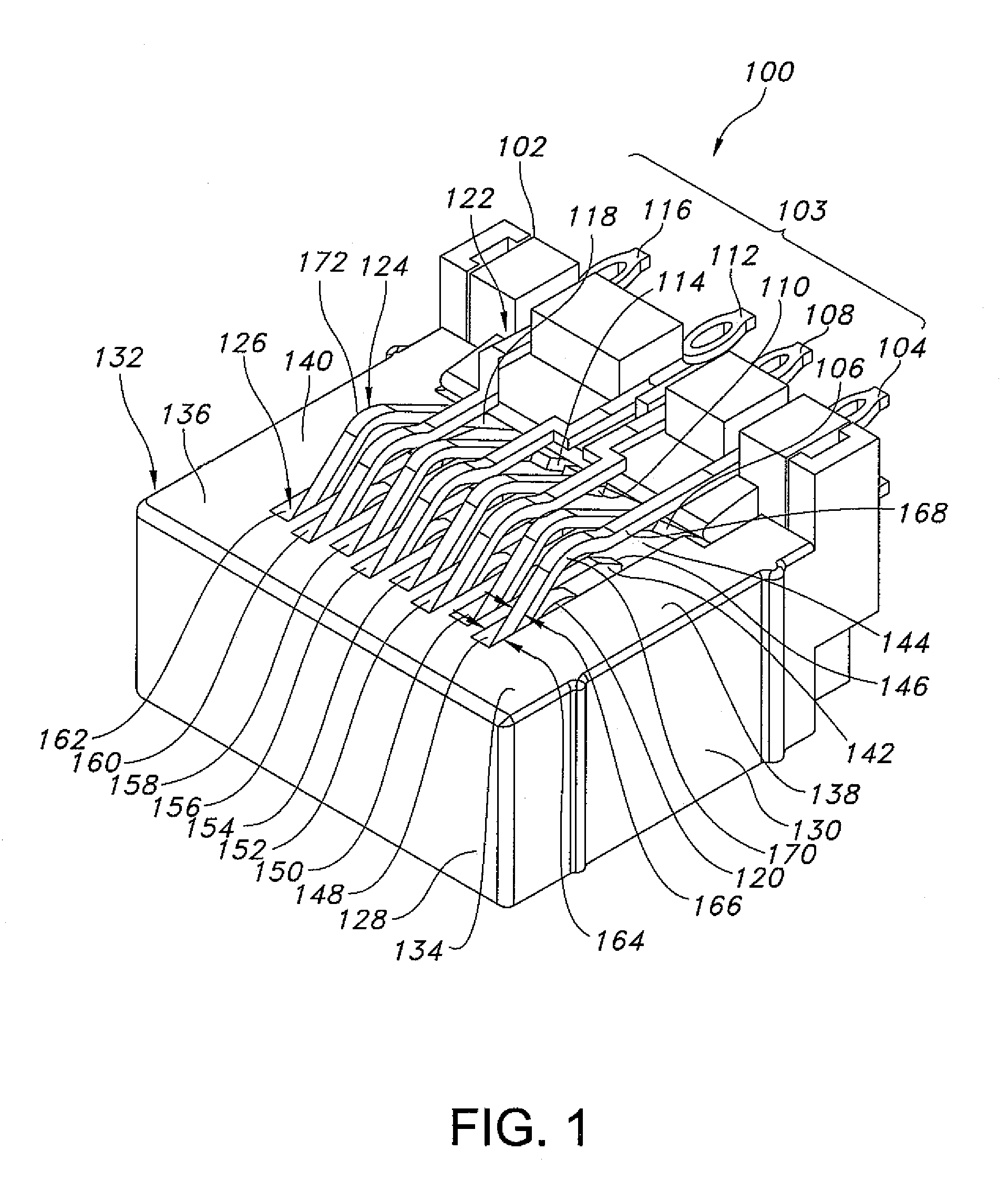
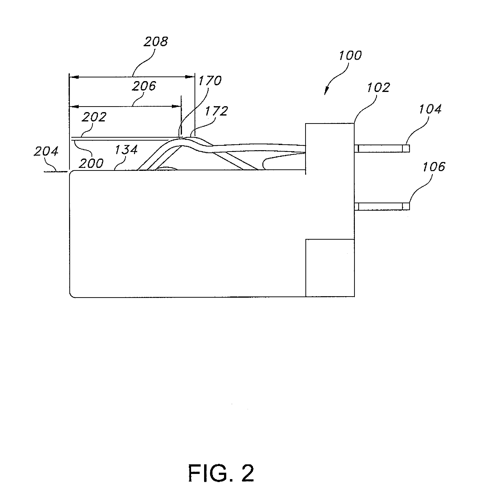
[0066]In accordance with embodiments of the present disclosure, advantageous modular insert assemblies are provided for use in voice / data communication systems, jack assemblies are provided that include such insert assemblies, and jack / plug combinations are provided that benefit from the advantageous structures, features and functions disclosed herein. The present disclosure provides methods for effecting voice / data communications wherein modular insert assemblies, jacks containing the disclosed insert assemblies and / or jack / plug combinations as described herein, are advantageously employed.

[0067]In accordance with embodiments of the present disclosure, modular insert assemblies are provided that include a secondary feature of noise compensation that allows interrupted communications across individual contacts, e.g., based upon interaction with corresponding plug contacts. Such modular insert assemblies may, for example, be incorporated in a telecommunications connector system that...


PUM


Abstract

An insert device for use in a communication jack includes a housing, and plug interface contacts mounted with respect to the housing. At least one plug interface contact includes a first length extent extending along a first axial path and defining a first reaction surface that includes a first electrically conductive surface. The insert device includes a reactance unit having a reactance circuit operable to reduce or compensate for an electrical noise associated with signals conducted by the plug interface contacts, and a plurality of interconnection elements. At least one interconnection element defines a second reaction surface that includes a second electrically conductive surface. The insert device moves the reactance circuit relative to the plug interface contact by sliding the second reaction surface across the first reaction surface, and presses the second electrically conductive surface against the first electrically conductive surface.

Description

BACKGROUND[0001]1. Technical Field[0002]The present disclosure is directed to communications connectors and, more particularly, to connection systems equipped and configured to address and / or compensate for electrical noise or crosstalk (e.g., near-end crosstalk or NEXT).[0003]2. Background Art[0004]Devices for interfacing with high frequency data transfer media are generally known. Modular jack housing inserts have been developed that facilitate interface with connectors, i.e., plugs, that in turn interact with unshielded twisted pair (UTP) media. UTP media finds widespread application in structured cabling applications, e.g., in local area network (LAN) implementations and other in-building voice and data communications applications. In a UTP cable, a plurality of twisted copper pairs are twisted together and wrapped with a plastic coating. Individual wires generally have a diameter of 0.4-0.8 mm. Twisting of the wires increases the noise immunity and reduces the bit error rate (B...

Claims


Application Information

Patent Timeline
Patent Type & Authority Patents(United States)
IPC IPC(8): H01R24/00
CPCH01R13/6464H01R13/6467Y10S439/941H01R24/64H05K2201/10189H05K1/0239H05K1/147H05K1/162H05K1/0228
Inventor AEKINS, ROBERT A.MARTICH, MARK E.
Owner ORTRONICS INC
Why Eureka
Try Eureka