Injection-locked pulsed laser with high wavelength stability

a pulsed laser and high wavelength stability technology, applied in the direction of optical radiation measurement, printers, instruments, etc., can solve the problems of difficult to generate an error signal with high sn, noise is likely to mix in the processing circuit, and the method using the buildup time may generate a control error, etc., to achieve good wavelength stability

Inactive Publication Date: 2009-10-27
CANON KK
View PDF9 Cites 8 Cited by
  • Summary
  • Abstract
  • Description
  • Claims
  • Application Information

AI Technical Summary

Benefits of technology

[0013]The present invention provides an injection-locked laser with good wavelength stability, an interferometer using the same, and an exposure apparatus.

Problems solved by technology

Unfortunately, the conventional control method using the buildup time may generate a control error when a factor (e.g., pump laser intensity jitter or pointing jitter) other than the oscillator length changes the buildup time.
Still worse, noise is likely to mix in a processing circuit for calculating the buildup time based on the output from the laser.
This makes it difficult to generate an error signal with high SN.
This produces a locking control error, resulting in laser characteristic deterioration such as intensity or wavelength jitter.

Method used


Image

  • Injection-locked pulsed laser with high wavelength stability
  • Injection-locked pulsed laser with high wavelength stability
  • Injection-locked pulsed laser with high wavelength stability

Examples


first embodiment

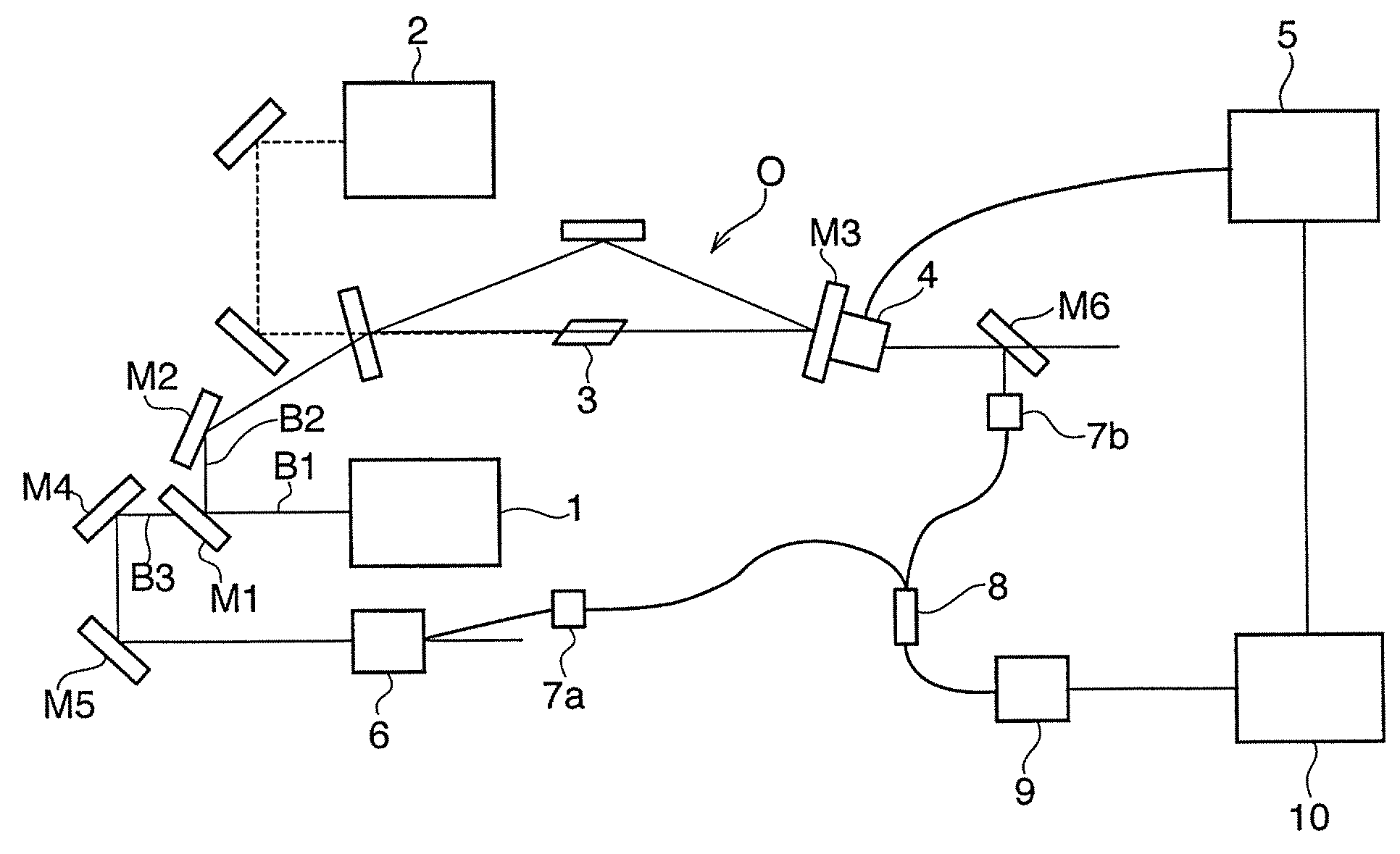
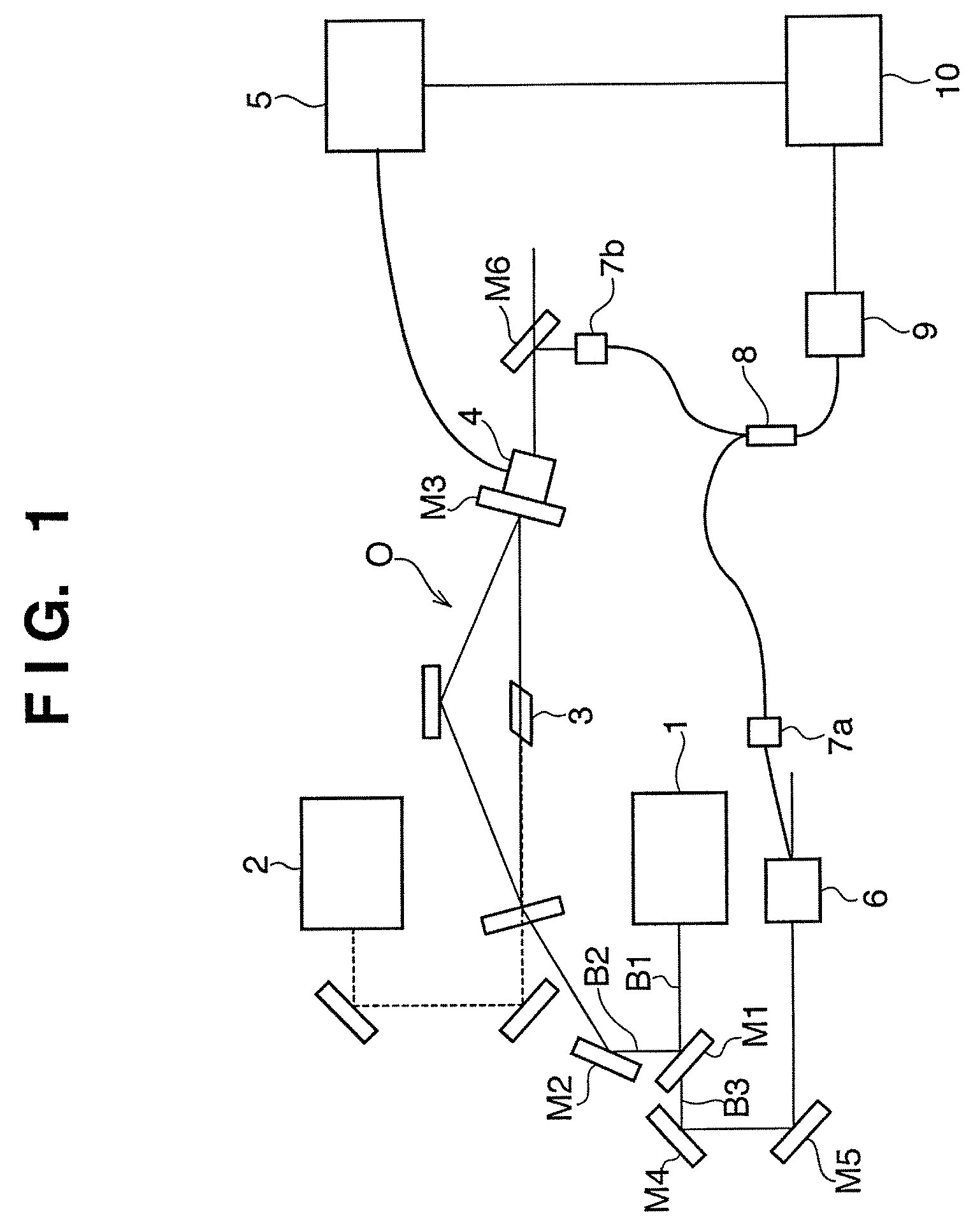
[0027]FIG. 1 is a view showing the schematic arrangement of an injection-locked pulse laser according to the first embodiment of the present invention. A light beam B1 output from a seed laser 1 is split into two light beams B2 and B3 by a half mirror M1. The light beam B2 reflected by the half mirror M1 is injected into a pulse oscillator O upon being reflected by a mirror M2. The pulse oscillator O is, preferably, of a ring type to avoid any influence of hole burning. A gain medium 3 is accommodated in the pulse oscillator O and can be excited by irradiating the inside of the oscillator O with laser light emitted by an excitation light source (pump laser) 2 arranged outside the pulse oscillator O. A PZT mount 4 mounts an output coupling mirror M3 of the oscillator O. A PZT controller 5 including an amplifier controls the PZT mount 4. This makes it possible to accurately control the optical path length of the oscillator O.

[0028]The light beam B3 output from the seed laser 1 and tra...

second embodiment

[0046]FIG. 4 is a view showing the schematic arrangement of an injection-locked pulse laser according to the second embodiment of the present invention. A light beam B1 output from a seed laser 1 is split into two light beams B2 and B3 by a half mirror M1. The light beam B2 reflected by the half mirror M1 is injected into a pulse oscillator O via a mirror M2. The pulse oscillator O is, preferably, of a ring type to avoid any influence of hole burning. A gain medium 3 made of a Ti:sapphire crystal is accommodated in the pulse oscillator O. The gain medium 3 can be excited by externally irradiating the oscillator O with a second harmonic wave emitted by an excitation light source (pump laser) 2 which is made of, for example, an Nd:YAG and has a wavelength corresponding to the absorption band of the Ti: sapphire. A PZT mount 4 mounts an output coupling mirror M3 of the oscillator O. A PZT controller 5 including an amplifier controls the PZT mount 4. This makes it possible to accurately...

third embodiment

[0066]FIG. 5 is a view showing the schematic arrangement of an interferometer according to the third embodiment of the present invention. The interferometer according to the third embodiment of the present invention incorporates the injection-locked pulse laser according to the second embodiment.

[0067]The interferometer according to the third embodiment of the present invention is suitable to, for example, inspect the imaging performance of a projection optical system built in an exposure apparatus such as a semiconductor exposure apparatus. The exposure apparatus uses an excimer laser of, for example, KrF or ArF as an illumination light source. For this reason, the projection optical system is designed to exhibit an optimal imaging performance at the wavelength of illumination light. An inspection apparatus for inspecting the imaging performance of the projection optical system executes inspection using a wavelength roughly equal to that of the illumination light as well. The third...


PUM


Abstract

An injection-locked laser is disclosed. The injection-locked laser comprises a seed laser, an oscillator into which a certain component of light output from the seed laser is injected as seed laser light, a frequency converter which shifts a frequency of the remaining component of the light output from the seed laser, a photodetector which detects light obtained by synthesizing the light output from the oscillator and the light output from the frequency converter, and a controller which controls an optical path length of the oscillator based on a beat signal component contained in the signal output from the photodetector.

Description

BACKGROUND OF THE INVENTION[0001]1. Field of the Invention[0002]The present invention relates to an injection-locked laser, an interferometer, an exposure apparatus, and a device manufacturing method.[0003]2. Description of the Related Art[0004]FIG. 7 is a view showing the schematic arrangement of a conventional injection-locked laser (see J. Rahn, “Feedback stabilization of an injection-seeded Nd:YAG laser”, App. Opt., 24, 940 (1985)). The injection-locked laser shown in FIG. 7 adopts an injection locking method of minimizing the buildup time.[0005]A pulse oscillator O for generating pulse light is, generally, of a ring type to avoid any influence of spectral hole burning. A PZT mount 4 mounts an output coupler of the pulse oscillator O. A PZT controller (PZT amplifier) 5 accurately drives the PZT mount 4. A laser gain medium 3 can employ, for example, a Ti:sapphire crystal. An excitation light source 2 made of, for example, Nd:YAG can be used to excite the crystal by irradiating t...

Claims


Application Information

Patent Timeline
Patent Type & Authority Patents(United States)
IPC IPC(8): G01J1/32
CPCG03F7/706H01S3/1394H01S3/005H01S3/083H01S3/094038H01S3/1398H01S3/1305H01S3/1392H01S3/10092
Inventor KURAMOTO, YOSHIYUKI
Owner CANON KK
Why Eureka
Try Eureka