Pipeline type A/D converter apparatus provided with precharge circuit for precharging sampling capacitor

a converter and capacitor technology, applied in power saving provisions, instruments, transmission systems, etc., can solve the problems of increasing the power consumption of an amplifier for charge and discharge of the capacitance, affecting the operation affecting the operation of the circuit design. , to achieve the effect of increasing the operating speed of the apparatus, reducing power consumption, and increasing power consumption

Inactive Publication Date: 2009-11-03
SEMICON TECH ACADEMIC RES CENT
View PDF7 Cites 36 Cited by
  • Summary
  • Abstract
  • Description
  • Claims
  • Application Information

AI Technical Summary

Benefits of technology

[0027]An object of the present invention is to solve the above problems and provide a pipeline type A / D converter apparatus capable of remarkably reducing power consumption or increasing the operating speed of the apparatus without increasing the power consumption as compared with the prior art techniques.
[0036]According to the pipeline type A / D converter apparatus of the present invention, the precharge circuit is provided that precharges the sampling capacitors before sampling so as to attain the predetermined output values in accordance with the digital input to output characteristics substantially adapted to the input to output characteristics of the A / D converter circuit parts that present output signals corresponding to the input signals to the A / D converter circuit parts. Therefore, the pipeline type A / D converter apparatus can be provided which is capable of remarkably reducing the power consumption or increasing the operating speed of the apparatus without increasing the power consumption as compared with the prior art techniques.

Problems solved by technology

On the other hand, A / D converters of analog circuits, which have become easily increased in speed by virtue of improvements in the basic performances of transistors, still need to cope with device variations on processes, deteriorations in the signal-to-noise ratio (hereinafter referred to as SNR) due to lowered voltages and so on, and this leads to difficulties in the circuit design for obtaining reliable performances.
In general, high-resolution pipeline type A / D converters need a large sampling capacitance to secure a high SNR, and it is unavoidable to increase the power consumption of an amplifier for charge and discharge of the capacitance.
In order to perform sampling at high speed for a large capacitance value, it is necessary to increase the bias current to perform quick charge and discharge, and an increase in the power consumption is a concern.
In order to sample a large capacitance value at higher speed, it is necessary to increase the bias current to quickly perform charge and discharge, and an increase in the power consumption becomes a concern.
Moreover, the pipeline type A / D converter of the second prior art needs a reset interval for erasing the sample history that might influence the settling response in the input of the amplifier and for common-mode feedback of the amplifier, and it is difficult to actually reduce the power by half.

Method used


Image

  • Pipeline type A/D converter apparatus provided with precharge circuit for precharging sampling capacitor
  • Pipeline type A/D converter apparatus provided with precharge circuit for precharging sampling capacitor
  • Pipeline type A/D converter apparatus provided with precharge circuit for precharging sampling capacitor

Examples


first preferred embodiment

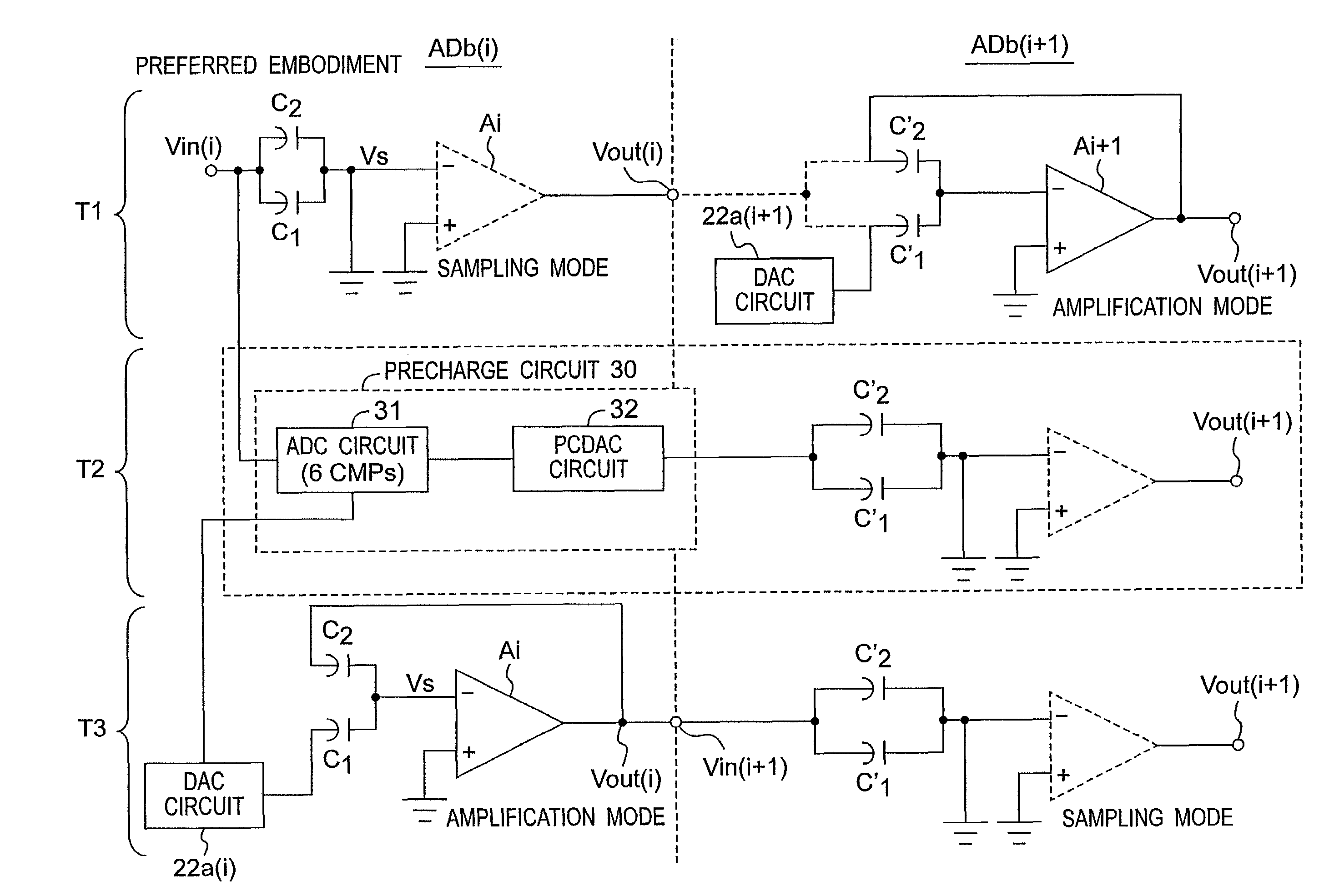
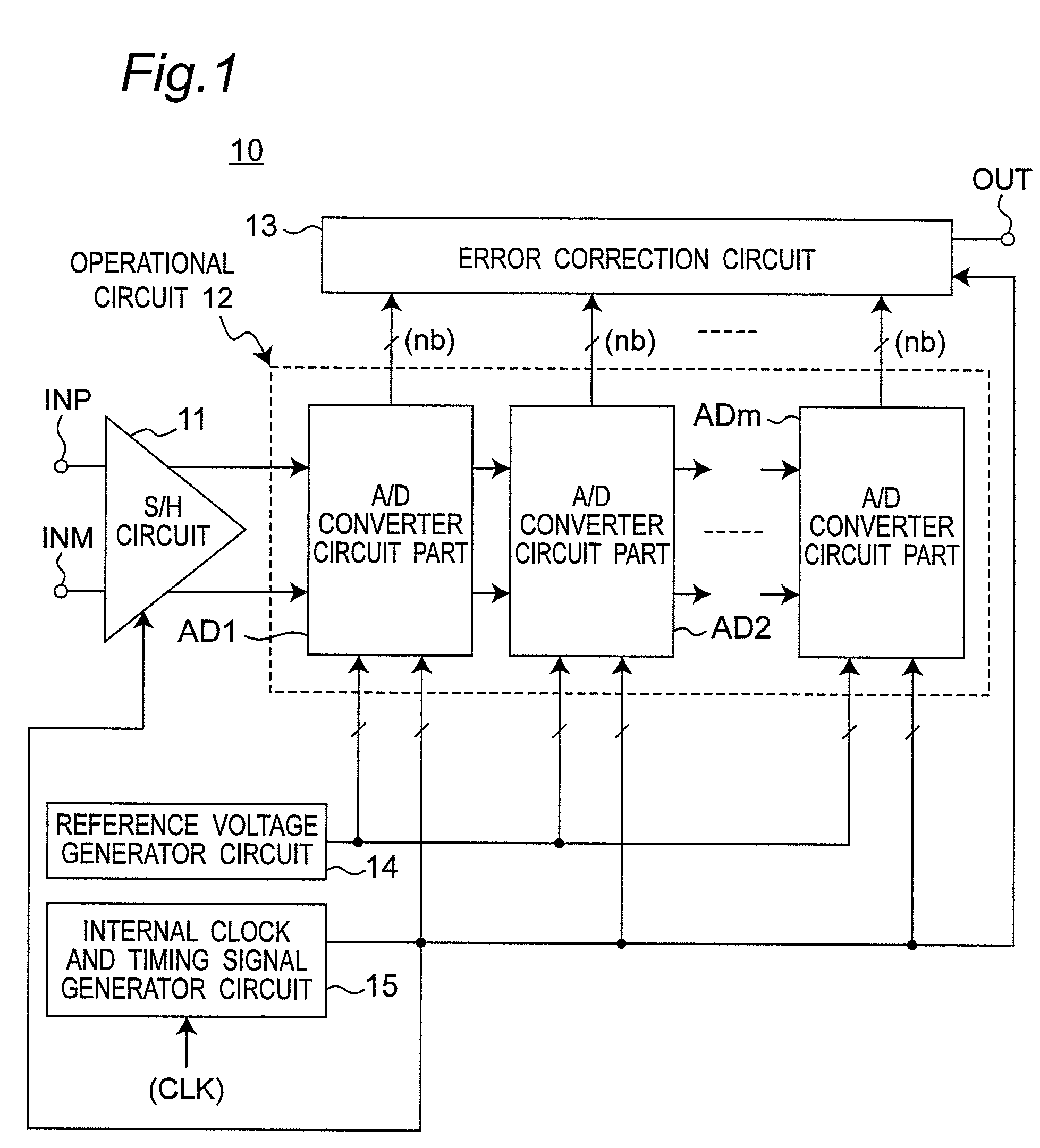
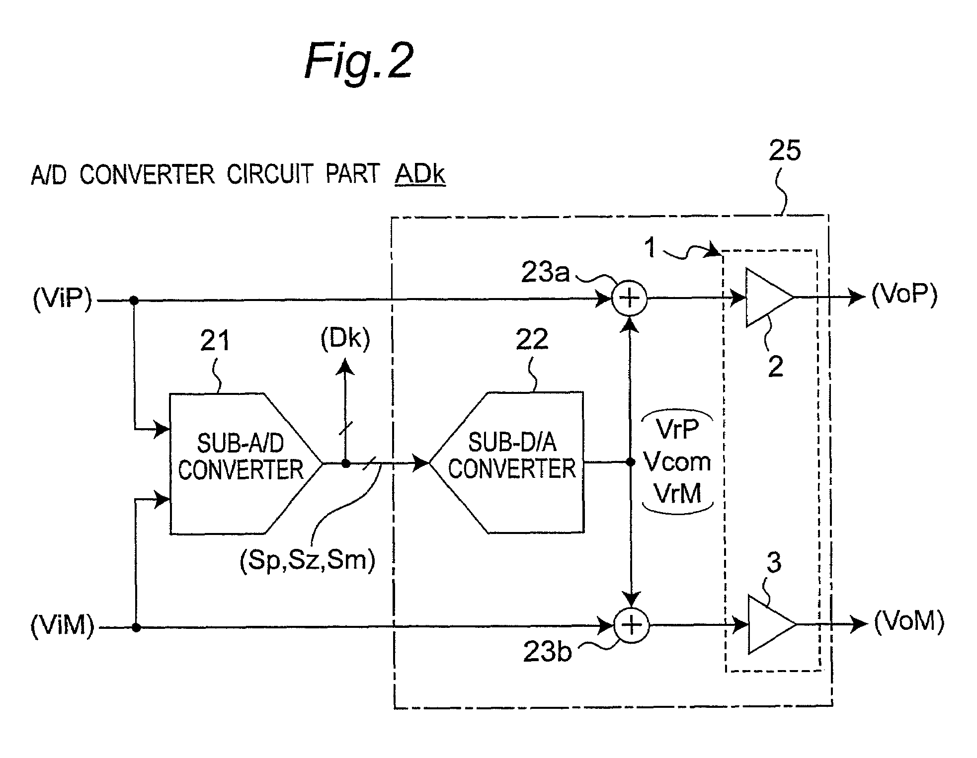
[0070]FIG. 1 is a block diagram showing a configuration of a pipeline A / D converter apparatus according to the first preferred embodiment of the invention, and FIG. 2 is a block diagram showing a configuration of an A / D converter circuit part ADk of FIG. 1. Referring to FIGS. 1 and 2, a structural example of a parallel pipeline type A / D converter apparatus employing a pseudo differential amplifier circuit 1 will be described hereinafter.

[0071]Referring to FIG. 1, a parallel pipeline type A / D converter apparatus 10 has a sample holding circuit (hereinafter referred to as a S / H circuit) 11 to which two analog signals having voltage waveforms symmetrical about a predetermined voltage of, for example, the ground voltage are inputted, an operational circuit 12 configured by pipeline type A / D converter circuit parts AD1 to ADm of m stages (where m is a natural and plural number), and an error correction circuit 13 that performs error correction of digital data outputted from the operation...

second preferred embodiment

[0121]FIG. 24 is a circuit diagram showing a detailed configuration of A / D converter circuit parts ADc(i) and ADc(i+1) according to the second preferred embodiment of the invention. FIG. 25 is a timing chart of the internal clock and timing signals showing operations of the A / D converter circuit parts ADc(i) and ADc(i+1) of FIG. 24.

[0122]In the A / D converter circuit parts ADb(i) and ADb(i+1) of the first preferred embodiment shown in FIG. 17, one operational amplifier Ai is shared by the MDAC circuits of two channels, i.e., an amplifier sharing system is used. In contrast to this, in the A / D converter circuit parts ADc(i) and ADc(i+1) of the second preferred embodiment of FIG. 24, two operational amplifiers Ai and Aia are used by the MDAC circuits of respective channels, i.e., a system of no amplifier sharing is used.

[0123]Referring to FIG. 24, the A / D converter circuit part ADc(i) includes the following:

[0124](1) an ADC circuit 31 that subjects input voltages VAin and VBin to A / D c...

third preferred embodiment

[0133]FIG. 26 is a circuit diagram showing a detailed configuration of A / D converter circuit parts ADd(i) and ADd(i+1) according to the third preferred embodiment of the invention. FIG. 27 is a timing chart of the internal clock and timing signals showing operations of the A / D converter circuit parts ADd(i) and ADd(i+1) of FIG. 26.

[0134]Although the first and second preferred embodiments are the A / D converter apparatuses of the two-channel system, the A / D converter circuit parts ADd(i) and ADd(i+1) of the third preferred embodiment are the circuit parts for an A / D converter apparatus of the one-channel system configured by one pair of capacitors 211 and 212 of the sampling capacitance Cs.

[0135]Referring to FIG. 26, the A / D converter circuit part ADd(i) includes the following:

[0136](1) an ADC circuit 31 that subjects the input voltage Vin to A / D conversion by using six comparators 41 to 46;

[0137](2) an MDAC circuit including a switched capacitor circuit, which has switches 201 to 203...


PUM


Abstract

In a pipeline type A / D converter apparatus including A / D converter circuit parts connected in cascade with each other and A / D converting a sample hold signal in a pipeline form, each A / D converter circuit part includes a pre-A / D converter circuit for A / D converting an input signal into a digital signal, and a multiplying D / A converter circuit for D / A converting the digital signal into an analog control signal, and D / A converting the input signal by sampling, holding and amplifying the input signal using a sampling capacitor based on the analog control signal. A precharge circuit precharges a sampling capacitor before sampling so as to attain a predetermined output value in accordance with a digital input to output characteristic substantially adapted to an input to output characteristic of each A / D converter circuit part that presents an output signal corresponding to the input signal to each A / D converter circuit part.

Description

BACKGROUND OF THE INVENTION[0001]1. Field of the Invention[0002]The present invention relates to a pipeline type A / D converter apparatus configured by, for example, VLSI, and provided with a precharge circuit.[0003]2. Description of the Related Art[0004]Under present circumstances where analog-digital consolidation system LSIs play great roles in accordance with developments in the communication and video technologies, a reduction in the power consumption of consolidation system LSIs is a matter of major concern. The progresses in the semiconductor fine processing technology have caused increases in the performance and integration of digital circuits and achieved efficient power reductions with lowered power voltages. On the other hand, A / D converters of analog circuits, which have become easily increased in speed by virtue of improvements in the basic performances of transistors, still need to cope with device variations on processes, deteriorations in the signal-to-noise ratio (he...

Claims


Application Information

Patent Timeline
Patent Type & Authority Patents(United States)
IPC IPC(8): H03M1/38
CPCH03M1/002H03M1/0695H03M1/442H03M1/361H03M1/164
Inventor KAWAHITO, SHOJIHONDA, KAZUTAKASHIMIZU, YASUHIDETANI, KUNIYUKIKURAUCHI, AKIRASUSHIHARA, KOJI
Owner SEMICON TECH ACADEMIC RES CENT
Why Eureka
Try Eureka