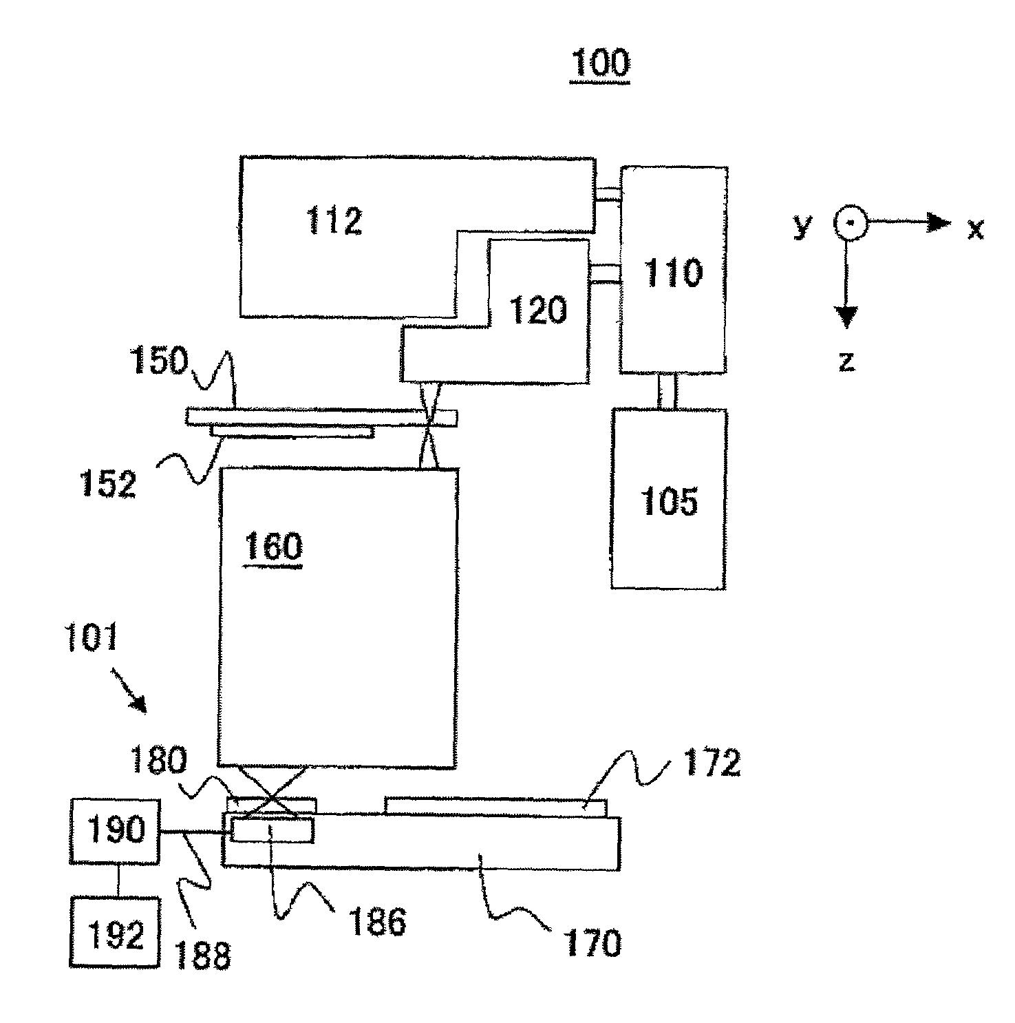
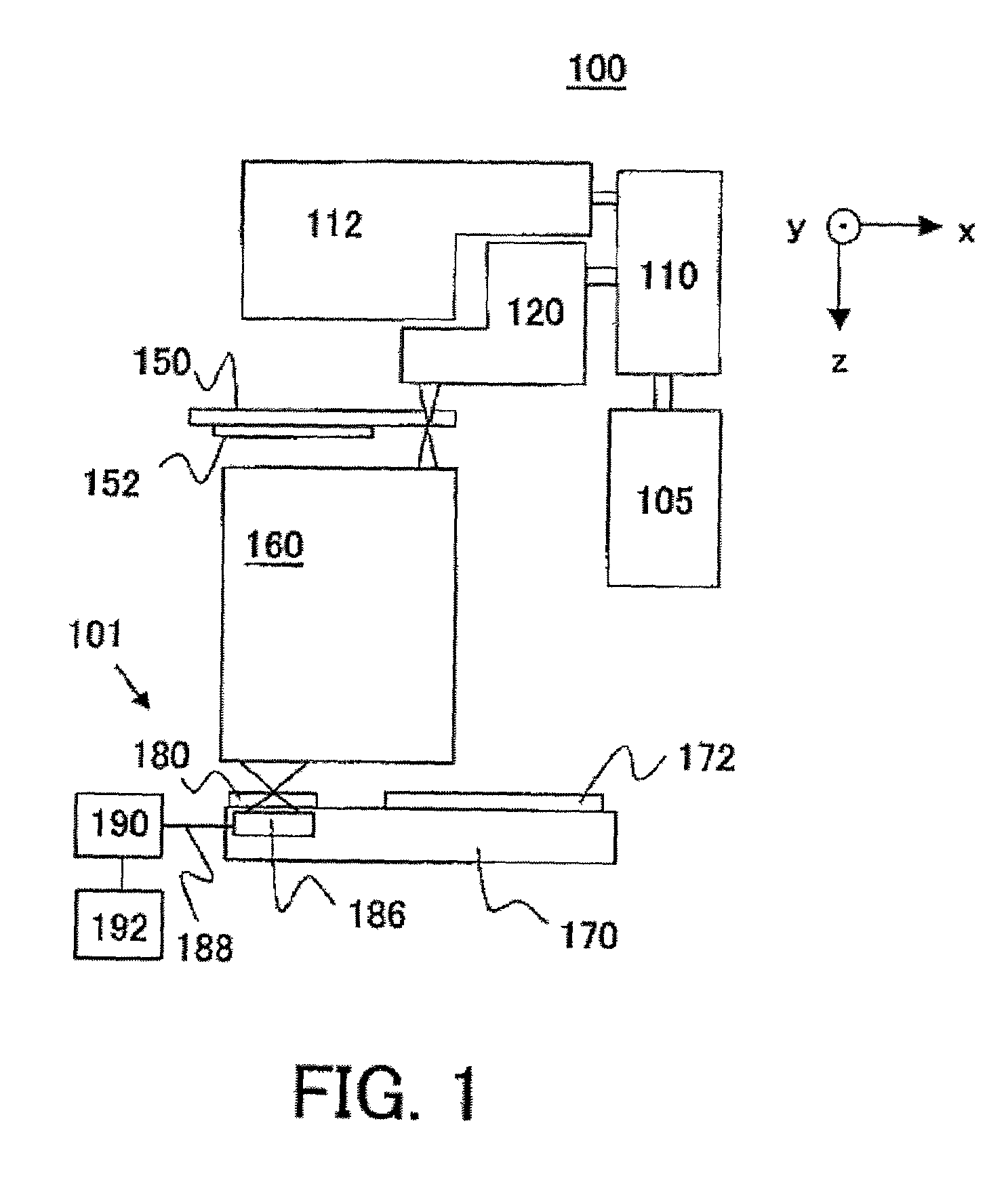
Exposure apparatus mounted with measuring apparatus
a technology of measuring apparatus and exposure apparatus, which is applied in the direction of optical radiation measurement, photomechanical apparatus, instruments, etc., can solve the problems of long measuring time, increase the cost of the entire system, and poor inspection reproducibility, and achieve the effect of short time and simple structur
- Summary
- Abstract
- Description
- Claims
- Application Information
AI Technical Summary
Benefits of technology
Problems solved by technology
Method used
Image
Examples
first embodiment
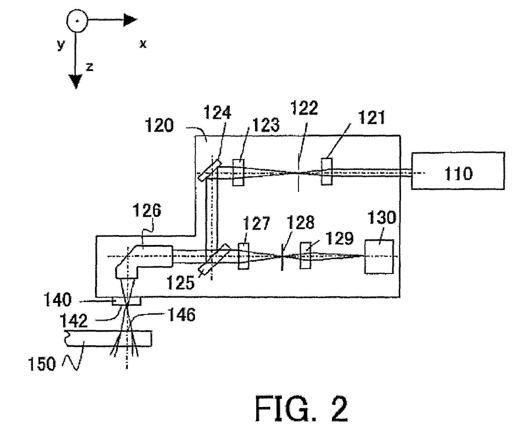
[0072]This embodiment is common to the first embodiment in that the measuring apparatus 101A uses the second illumination apparatus 120A that serves as an alignment scope and simplifies the structure. the optical system 121 to the image pickup means 130 in the second illumination optical system 120A have similar functions, although a condensing point of the condenser lens 126 is set to the first mask 142A on the mask stage 150.
[0073]The measuring apparatus 101A uses the light splitting means146 shown in FIG. 4, but is different from the first embodiment in that the light splitting means 146 is provided between the condenser lens 126 and the half mirror 125 in the second illumination optical system 129 shown in FIG. 2 (or uses the second illumination optical system 120A). As a result, plural lights that are amplitude-split by the light splitting means 146 enter the condenser lens 126. The diffraction grating 148a corresponds to the slit 144c and window 145a in the first mask 142A, an...
third embodiment
[0084]Referring now to FIGS. 10 and 11, a description will be given of the measuring apparatus 101B according to the present invention. The measuring apparatus 101B differs from the measuring apparatuses 101 and 101A in a first mask 142A and a configuration of a light splitting means 146. Those elements, which are the corresponding elements in FIGS. 2 and 9, are designated by the same reference numerals, and a duplicate description thereof will be omitted. When the measuring apparatus 101B is used, the reference numeral 101 in FIG. 1 is replaced with 101B. Here, FIG. 11 is an optical-path diagram of the second illumination optical system 120, the light splitting means 146 and the first mask 142A in the measuring apparatus 101B.
[0085]This embodiment is common to the first embodiment in that the measuring apparatus 101B uses the second illumination apparatus 120 that serves as an alignment scope and simplifies the structure. The optical system 121 to the image pickup means 130 in the ...
fourth embodiment
[0117]Referring now to FIG. 14, a description will be given of an operation of the measuring apparatus 101D. First, the wave front aberration of the projection optical system 160 in the x direction is measured (step 1102). Similar to the step 1102 in the fourth embodiment, the light emitted from the light source section 105 is deflected to the second illumination optical system 120C for measuring the imaging performance, via the deflection optical system 110. The light from the deflection optical system 110 is condensed into the optical system 121 for the illumination optical system, and irradiated onto the field stop 122. The field stop 122 has a size enough to irradiate a pattern on the substrate for the first mask 142A, which will be described later. The light from the field stop 122 is collimated by the optical system 123, deflected by the deflection mirror 124 and half mirror 125, and introduced into the condenser lens 126. The condenser lens 126 condenses the light into the fi...
PUM
| Property | Measurement | Unit |
|---|---|---|
| wavelength | aaaaa | aaaaa |
| wavelength | aaaaa | aaaaa |
| angle | aaaaa | aaaaa |
Abstract
Description
Claims
Application Information
 - R&D
- Intellectual Property
- Life Sciences
- Materials
- Tech Scout
- Unparalleled Data Quality
- Higher Quality Content
- 60% Fewer Hallucinations
Browse by: Latest US Patents, China's latest patents, Technical Efficacy Thesaurus, Application Domain, Technology Topic, Popular Technical Reports.
© 2025 PatSnap. All rights reserved.Legal|Privacy policy|Modern Slavery Act Transparency Statement|Sitemap|About US| Contact US: help@patsnap.com


