

Linearly polarized antenna and radar apparatus using the same
a linear polarization and antenna technology, applied in the structure of the antenna earthing, the resonance antenna, etc., can solve the problems of large residual carrier generation, difficult to make the radiation power density 20 db, and interference with eess and the like, so as to reduce radio interference, suppress the generation of surface waves, and prevent the effect of fluctuation in the characteristic caused by the influence of the surface wave between the antenna elements
- Summary
- Abstract
- Description
- Claims
- Application Information
AI Technical Summary
Benefits of technology
Problems solved by technology
Method used
Image

Examples
first embodiment
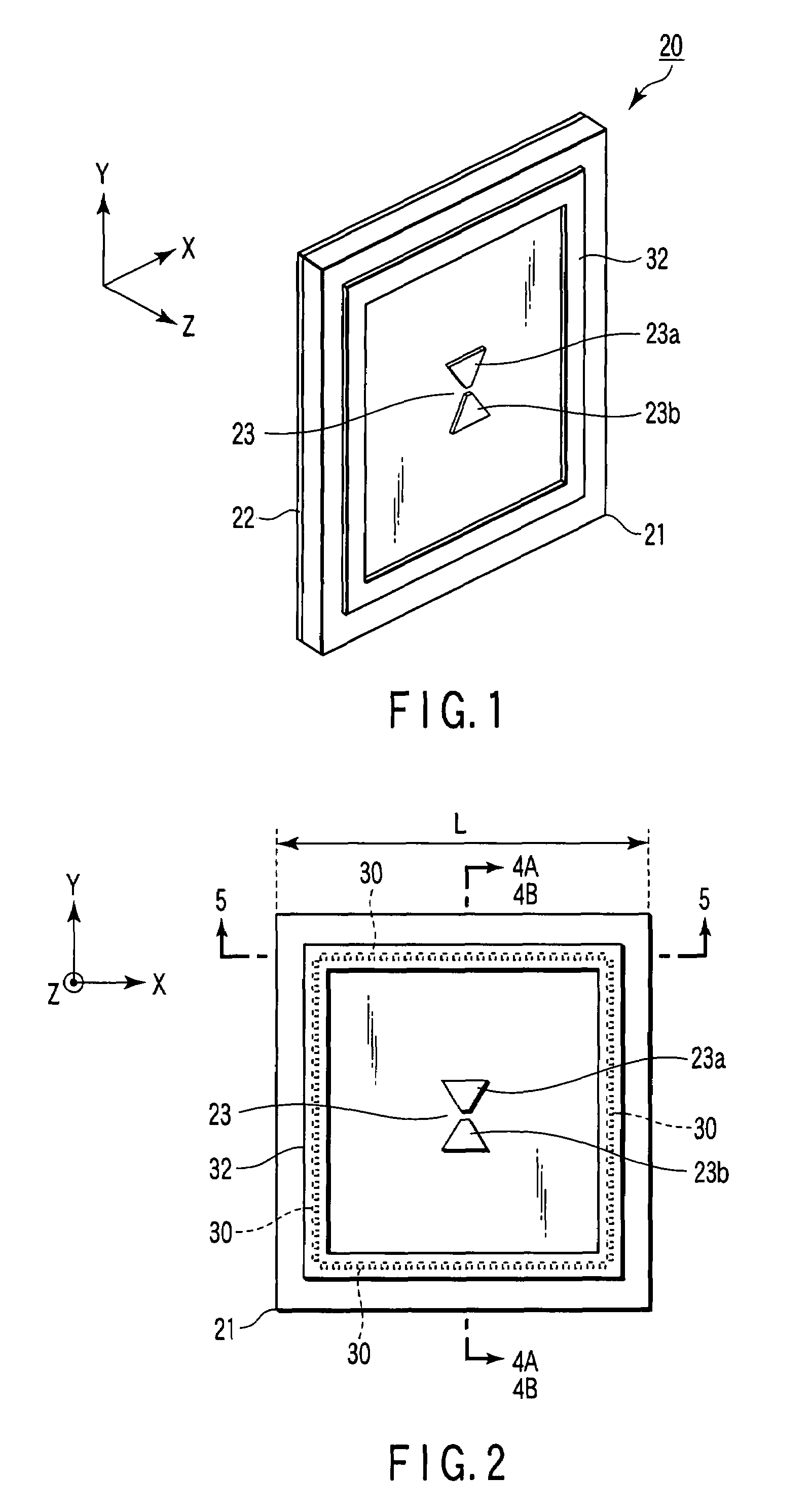
[0111]FIGS. 1 to 5 show a basic structure of a linearly polarized antenna 20 according to a first embodiment of the invention.
[0112]FIG. 1 is a perspective view showing a configuration of the linearly polarized antenna according to the first embodiment of the invention.
[0113]FIG. 2 is a front view showing the configuration of the linearly polarized antenna according to the first embodiment of the invention.
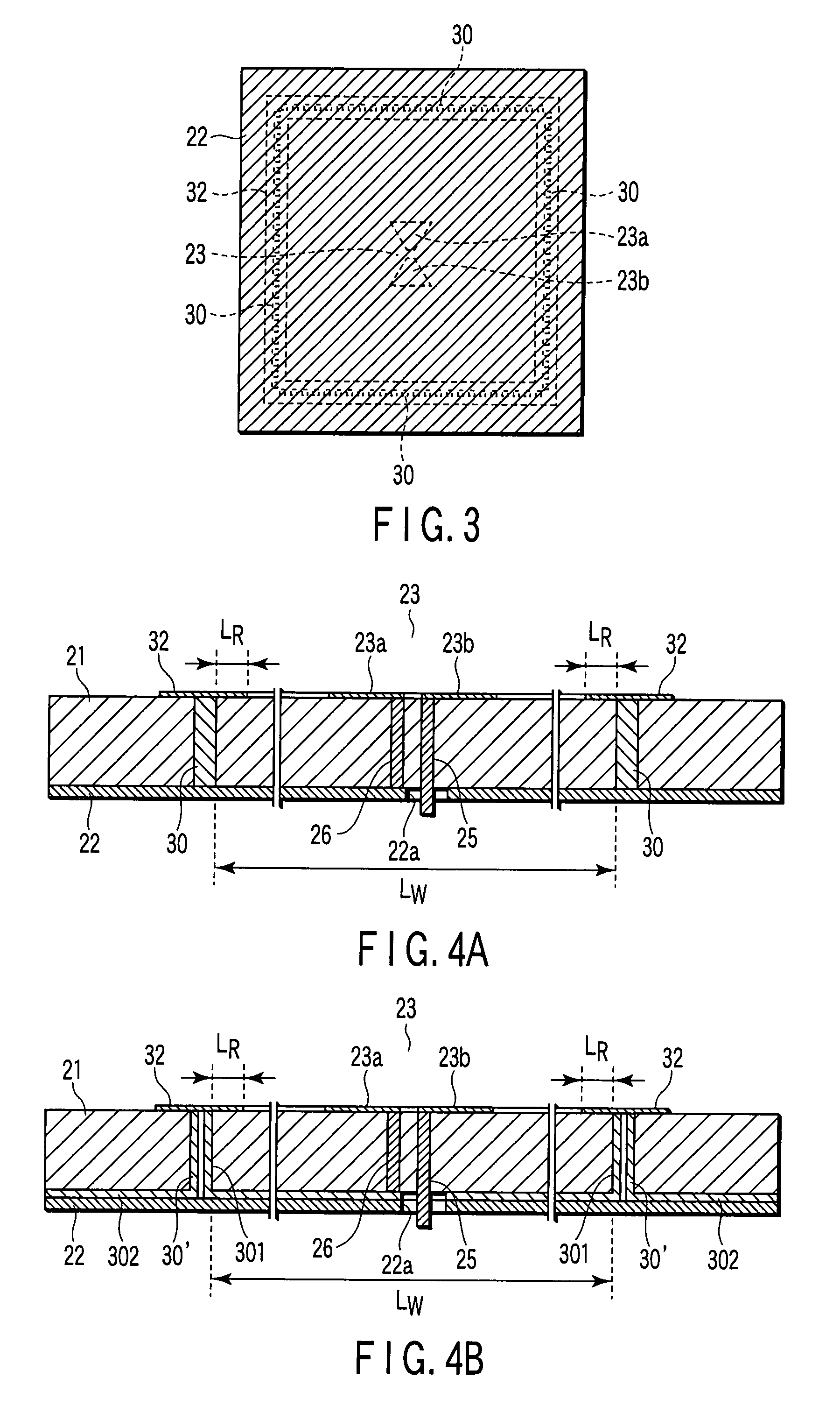
[0114]FIG. 3 is a rear view showing the configuration of the linearly polarized antenna according to the first embodiment of the invention.
[0115]FIG. 4A is an enlarged sectional view taken on a line 4A-4A of FIG. 2.
[0116]FIG. 4B is an enlarged sectional view taken on a line 4B-4B in a modification of FIG. 2.
[0117]FIG. 5 is an enlarged sectional view taken on a line 5-5 of FIG. 2.
[0118]Basically, as shown in FIGS. 1 to 5, the linearly polarized antenna of the invention includes a dielectric substrate 21, a ground conductor 22, a linearly polarized antenna element 23, a plurality of...
second embodiment
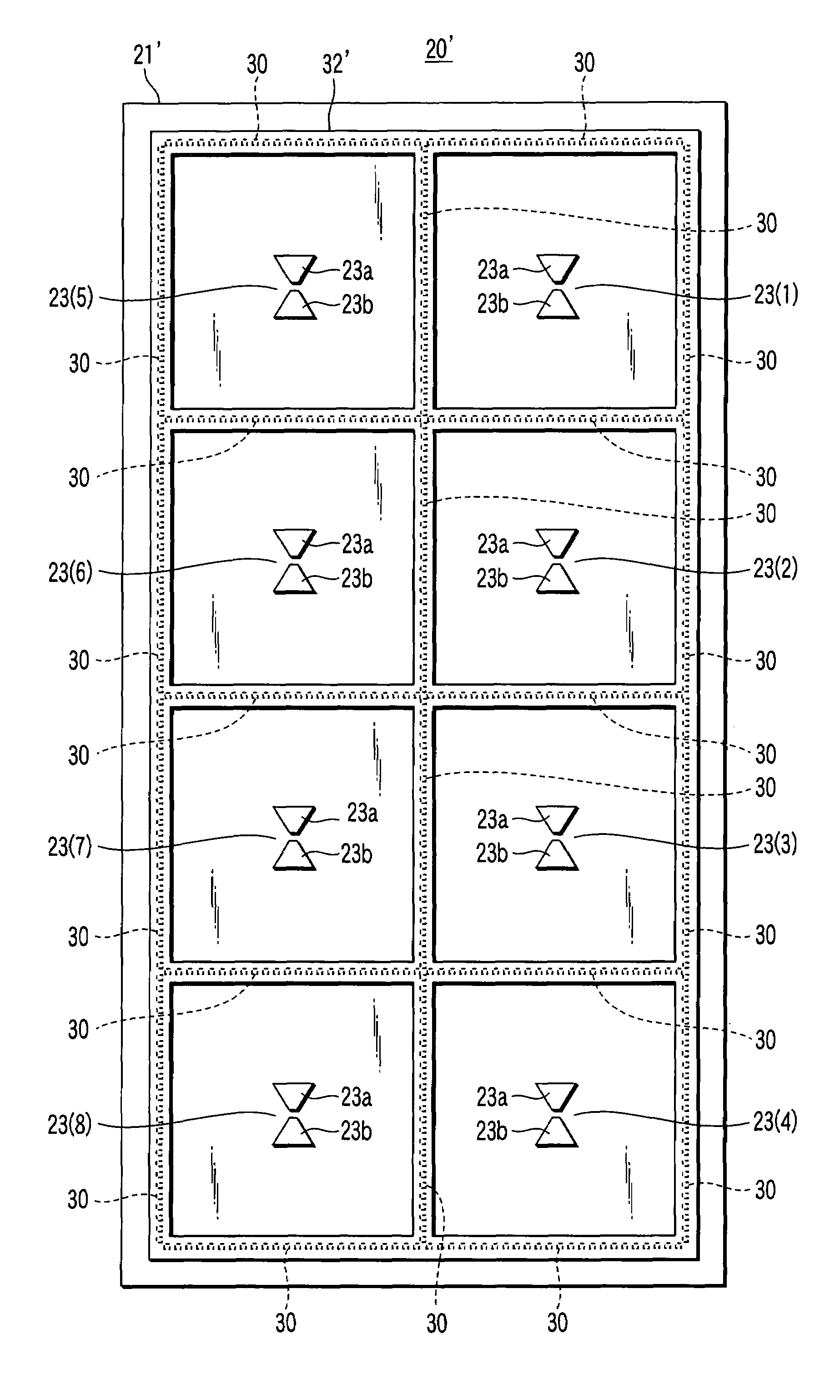
[0162]The linearly polarized antenna 20 of the first embodiment may be arrayed in the case where the gain necessary for the UWB radar runs short or in the case where the beam needs to be narrowed.
[0163]FIGS. 9 to 11 show a configuration of an arrayed linearly polarized antenna 20′ which is a second embodiment of the linearly polarized antenna according to the invention.
[0164]FIG. 9 is a front view showing a configuration of an array to which the linearly polarized antenna according to the second embodiment of the invention is applied.
[0165]FIG. 10 is a side view showing the configuration of the array to which the linearly polarized antenna according to the second embodiment of the invention is applied.
[0166]FIG. 11 is a rear view showing the array to which the linearly polarized antenna according to the second embodiment of the invention is applied.
[0167]In the linearly polarized antenna 20′ according to the second embodiment, a plurality sets of the antenna element 23 of the first ...
third embodiment
[0194]A third embodiment of a linearly polarized antenna according to the invention in which a configuration to broaden the band of the notch is adopted will be described below.
[0195]FIGS. 12A to 12C are enlarged front views showing a configuration of a main part to which a linearly polarized antenna 20 according to the third embodiment of the invention is applied and configurations of two different modifications.
[0196]Each of the linearly polarized antenna 20 shown in FIGS. 12A, 12B, and 12C is characterized in that the width of a conducting rim 32 is unevenly formed.
[0197]The linearly polarized antenna 20 of FIG. 12A shows an example in the case where a wave shape is formed as any shape which can be taken to unevenly form the width of the conducting rim 32.
[0198]The linearly polarized antenna 20 of FIG. 12B shows an example in the case where an arc is formed as any shape which can be taken to unevenly form the width of the conducting rim 32.
[0199]The linearly polarized antenna 20 ...
PUM
 Abstract
Description
Claims
Application Information