Process for making ceramic insulation
a technology of ceramic insulation and process, applied in the field of ceramic insulation production methods, can solve the problems of limiting the diffusion (permeability) or molten metal of gas, glass, pore size, etc., and achieve the effect of low cost and superior performan
- Summary
- Abstract
- Description
- Claims
- Application Information
AI Technical Summary
Benefits of technology
Problems solved by technology
Method used
Image
Examples
example 1
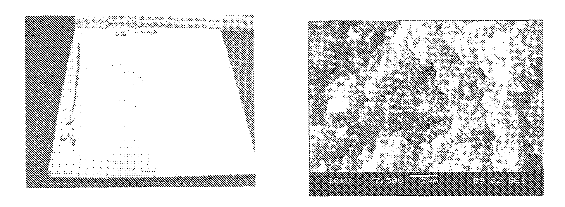
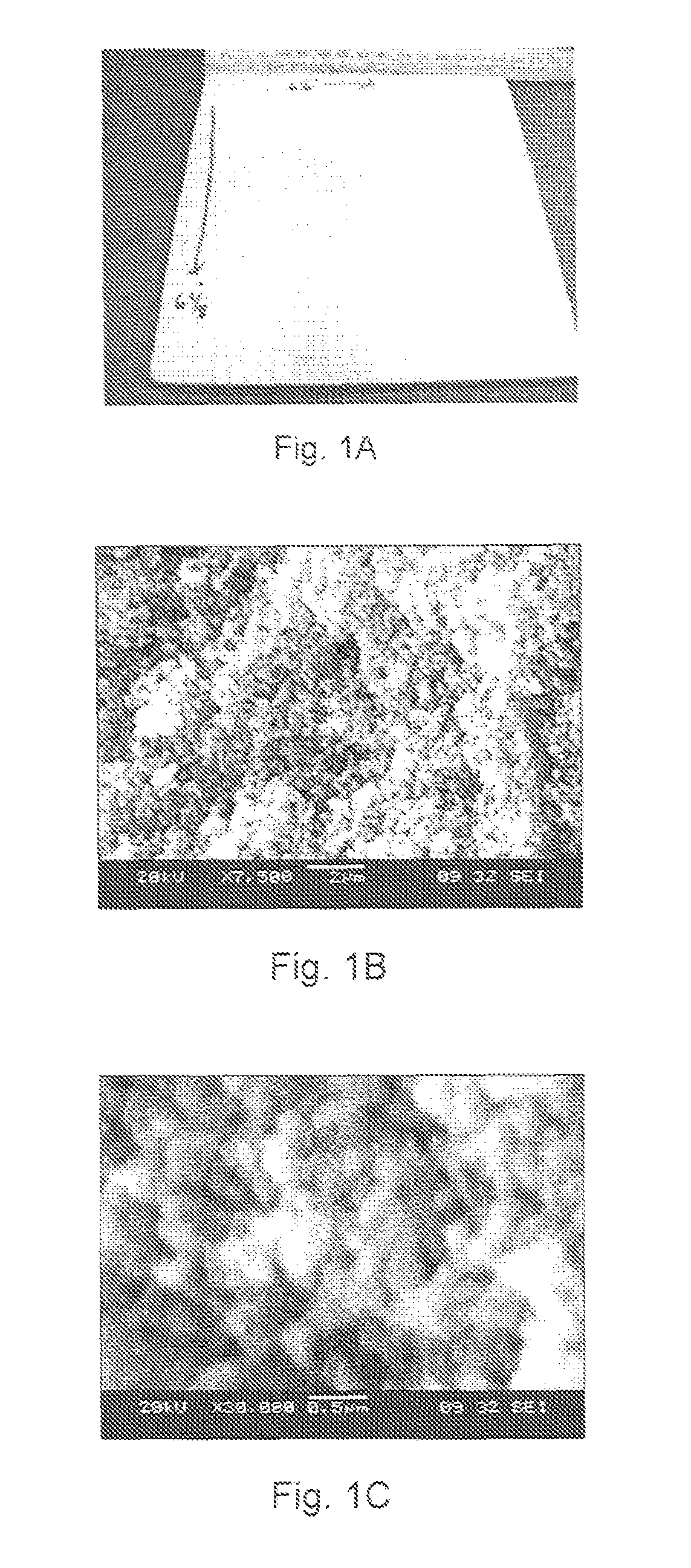
[0061]High purity (99.99%) alumina powder (with low surface area) having an average particle size of 2 μm was suspended in water using dispersants, binders, and plasticizers at 18 vol % solids. The suspension was paint-shaken with a small amount of alumina media to improve and speed up the dispersion process. A pore-former in the form of carbon was added at three different levels (i) 60 vol. %; (ii) 40 vol. %; and (iii) 0 vol. %. Phosphoric acid was added to the mix to obtain the final slip. The resulting slurry was poured into the mold, dried and fired to 800° C. The resulting insulation material with 60 vol. % pore-former is illustrated in FIGS. 1A-1C. Table I below summarizes the sample properties.
[0062]
TABLE IProperties for Sample with 60 vol. % pore-formerValueDensity (g / cc)0.80 g / ccFlexural Strength (MPa)Thermal Conductivity (W / m · K) at 800° C.0.3 W / m · K
This technique allows for incorporating very fine porosity (≦1 micron) into the ceramic matrix thus making it a very effect...
example 2
[0063]High purity alumina powder with an average particle size of 5 μm was suspended in water using dispersants, binders, and plasticizers at 45 vol. % solids. Dispersants, binders, and plasticizers were added in the range of 9.0 wt. % to obtain a fully dispersed slurry with low viscosity (<1000 cP). Phosphoric acid was added and the slurry was intimately mixed at room temperature using a mixer. No external heating was applied during the mixing process. While mixing the slurry with the acid, a modest temperature increase was observed as a result of the mixing process. The ratio of the weight of acid to total weight of all alumina-based solids was less than 1.0. The slurry was then poured into a desired mold and allowed to dry in an oven at 40° C. The drying temperature can range from room temperature to 100° C. but preferably between 22° C.-70° C. The green component, after drying, was fired at a temperature of about 900° C. for 12 hours.
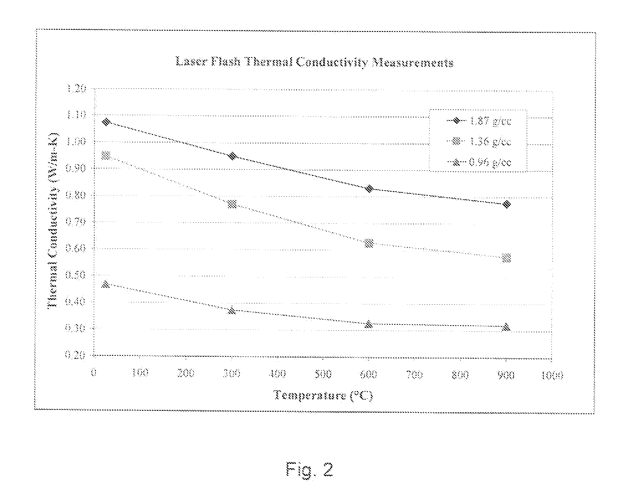
Table II below outlines the strength as a fun...
example 3
[0065]A slip is made according to the procedure of Example 2. A portion of the 100% alumina slip is poured into the mold and left to dry. A quantity of silicon carbide powders is added to the leftover portion of the alumina slip in an amount of about 50 vol. %. This second alumina-silicon carbide (50 / 50) (by volume) slip is then poured on top of the first alumina cast sample and left to dry. A schematic of the multilayered final product 20 using this technique is shown in FIG. 4. The multilayered product 20 has two layers—bottom layer 22 is 100% alumina, while the top layer 24 is a 50 / 50 mixture of alumina and silicon carbide. It will be appreciated that this technique may be used to prepare multilayered insulation having a variety of different compositions and properties.
PUM
| Property | Measurement | Unit |
|---|---|---|
| mean particle size | aaaaa | aaaaa |
| temperature | aaaaa | aaaaa |
| temperature | aaaaa | aaaaa |
Abstract
Description
Claims
Application Information
 - R&D
- Intellectual Property
- Life Sciences
- Materials
- Tech Scout
- Unparalleled Data Quality
- Higher Quality Content
- 60% Fewer Hallucinations
Browse by: Latest US Patents, China's latest patents, Technical Efficacy Thesaurus, Application Domain, Technology Topic, Popular Technical Reports.
© 2025 PatSnap. All rights reserved.Legal|Privacy policy|Modern Slavery Act Transparency Statement|Sitemap|About US| Contact US: help@patsnap.com


