Method of recovering carbon dioxide from a synthesis gas stream

a carbon dioxide and gas stream technology, applied in the field of recovering carbon dioxide from a synthesis gas stream, can solve the problem that the recovery within the absorption column will tend to fall to low levels, and achieve the effect of promoting the disengagement of carbon dioxid

Active Publication Date: 2009-12-15
PRAXAIR TECH INC
View PDF16 Cites 24 Cited by
  • Summary
  • Abstract
  • Description
  • Claims
  • Application Information

AI Technical Summary

Benefits of technology

[0022]It is to be noted that where the synthesis gas is utilized at a relatively low temperature and without steam, generally speaking, 50 percent or less of the carbon dioxide can be recovered. By adding steam, more of the carbon dioxide can be recovered because more heat is being transferred to promote the disengagement of the carbon dioxide from the solvent. Where superheated steam from the steam generation system of the facility is mixed directly with the synthesis gas stream, the steam content of the synthesis gas can be raised to a superheated level allowing for some latitude in the location of the absorption system with respect to the point at which the synthesis gas is removed. The same is true where a saturator is used in that the synthesis gas stream and added steam can be heated to again superheat the steam content of the synthesis gas stream. As will be discussed, each specific method can be utilized in an economically advantageous manner.

Problems solved by technology

However, where the synthesis gas is treated at a lower temperature, recoveries within the absorption column will tend to fall off to low levels of about 50 percent or less.
The use of the synthesis gas at a lower temperature such as suggested by the Air Liquide, Haldor Topsoe paper presents a problematical integration in a retrofit situation because the absorption system must be located physically close to the existing equipment to avoid condensation of the water content of the synthesis gas which at the point of extraction of the synthesis gas is at or near its dew point.

Method used


Image

  • Method of recovering carbon dioxide from a synthesis gas stream
  • Method of recovering carbon dioxide from a synthesis gas stream
  • Method of recovering carbon dioxide from a synthesis gas stream

Examples


Embodiment Construction

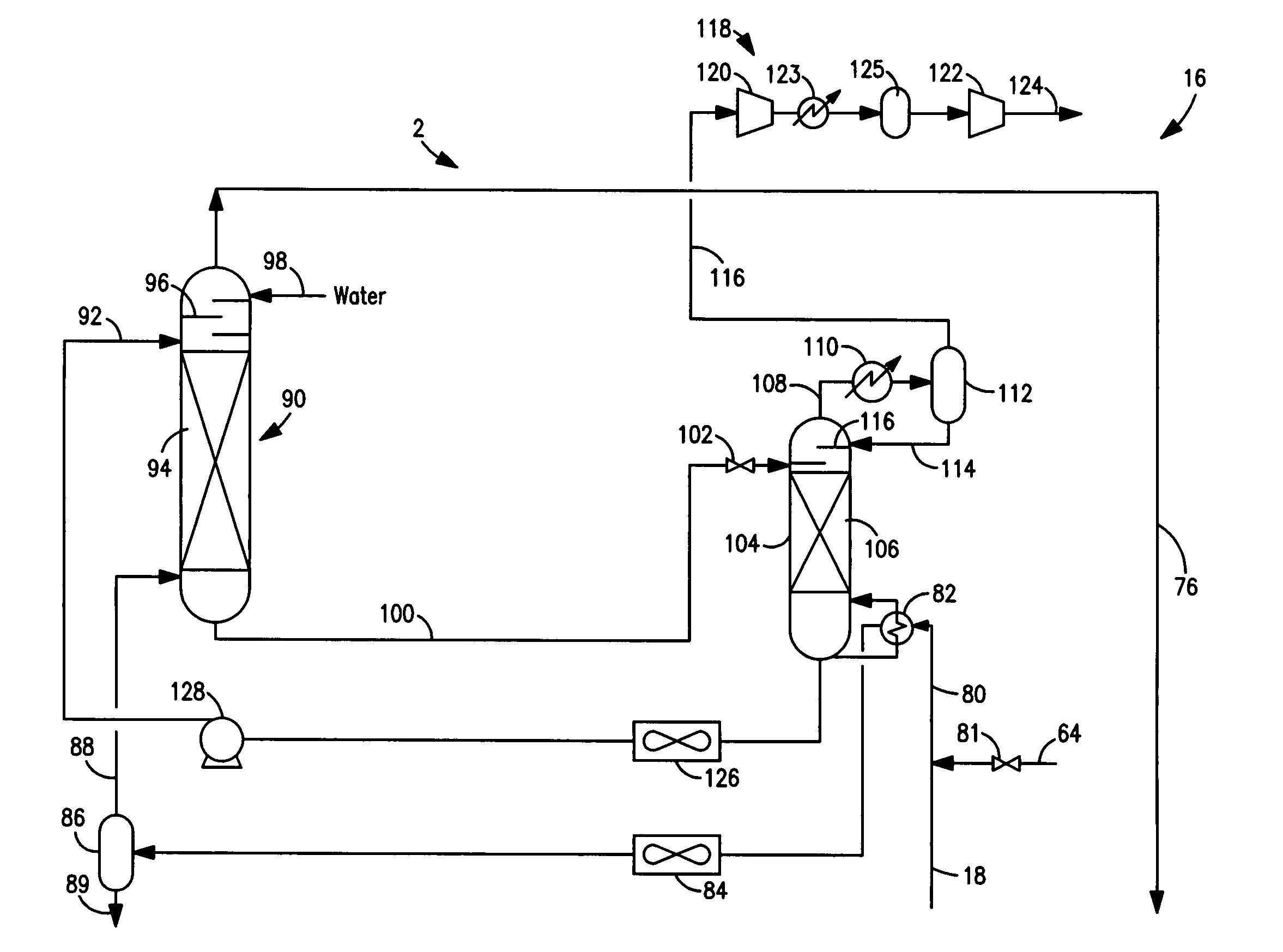
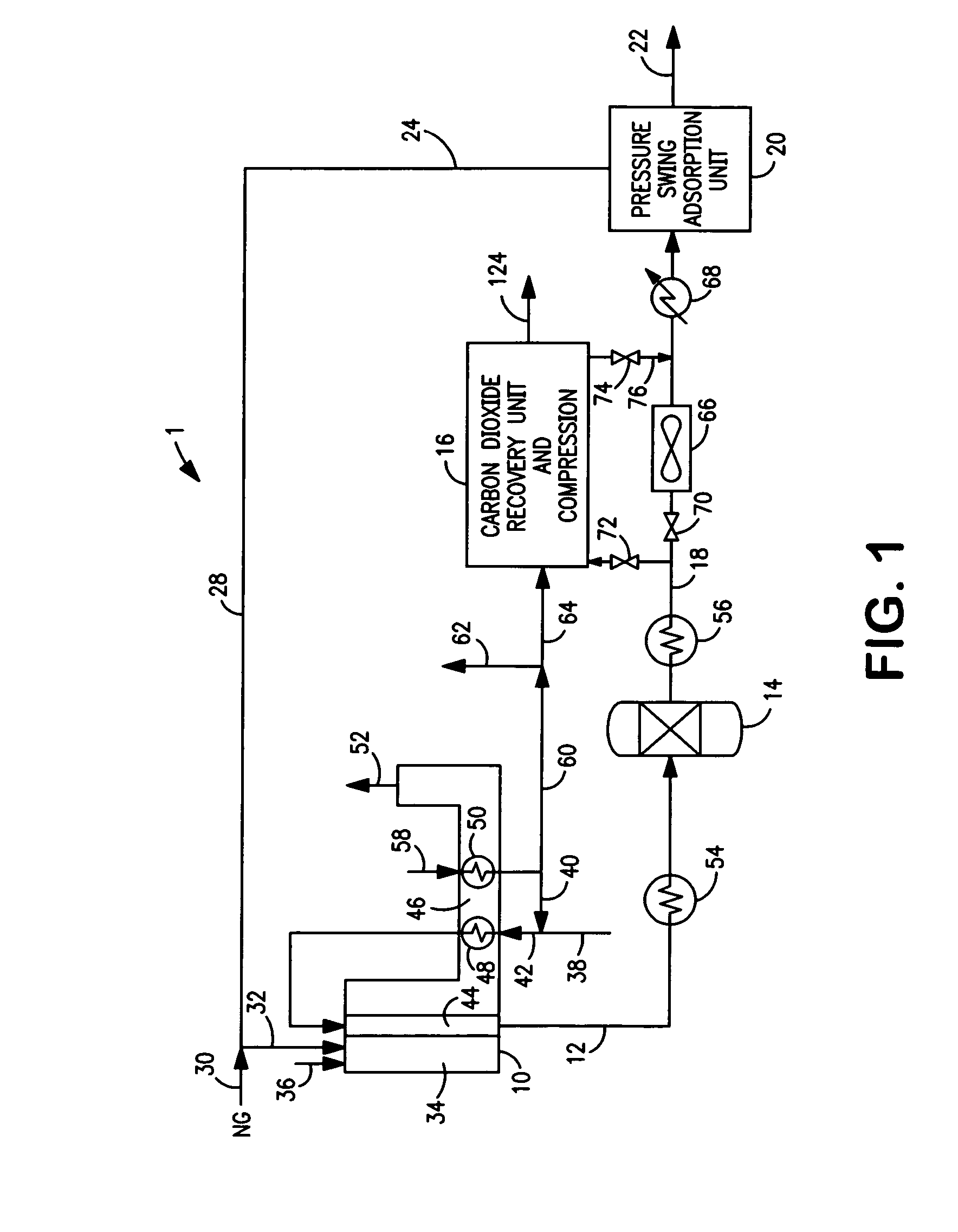
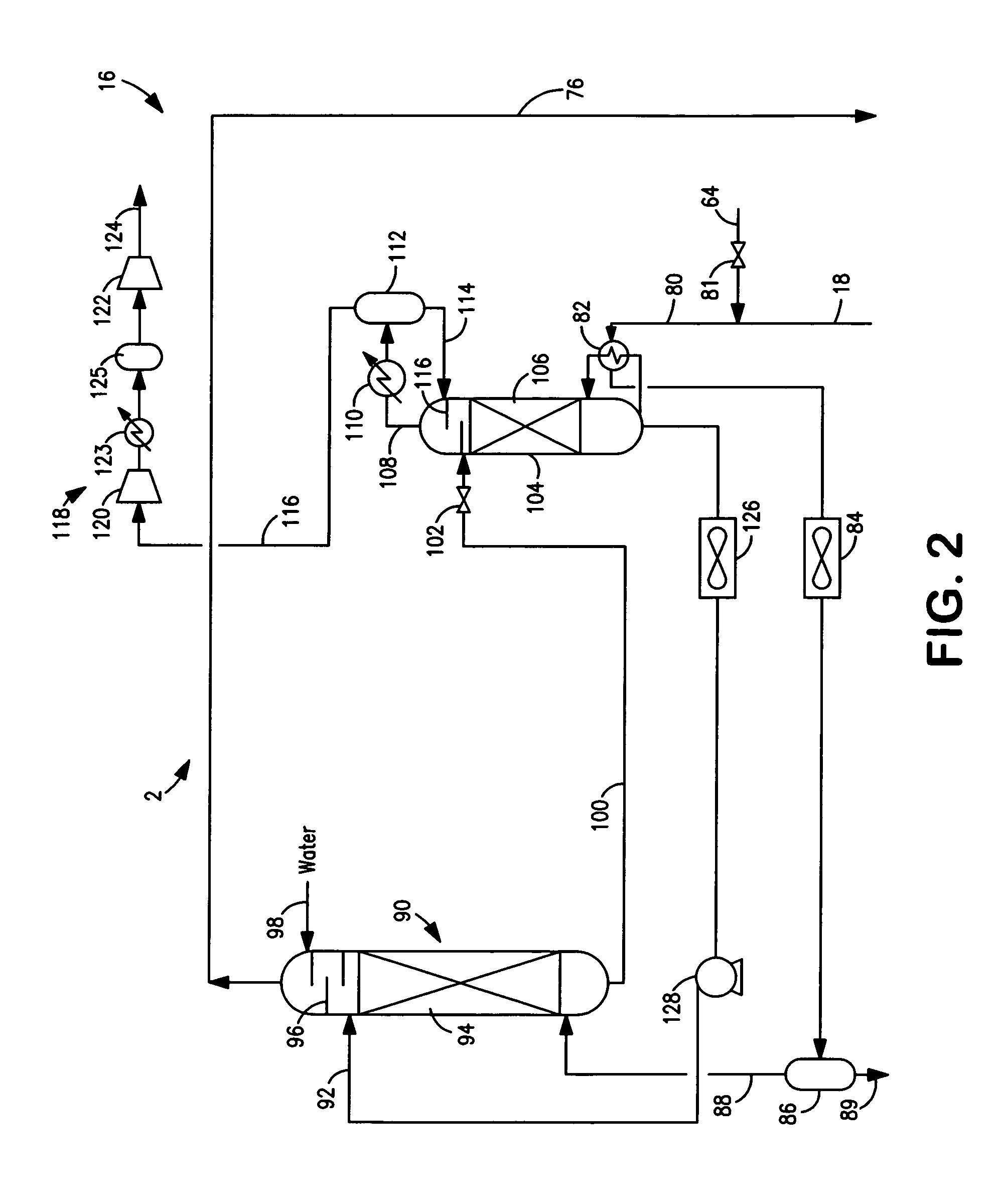
[0038]With reference to FIG. 1 a facility 1 is illustrated having a steam methane reformer 10 for generating a crude synthesis gas stream 12, a downstream water-gas shift reactor 14 and a carbon dioxide absorption system 16 for recovering carbon dioxide from a synthesis gas stream 18 in which the hydrogen content has been upwardly shifted by water-gas shift reactor 14.

[0039]In facility 1, a pressure swing adsorption unit 20 is provided to purify the hydrogen into a hydrogen product stream 22 in a known manner. For example, hydrogen adsorption unit 20 can have adsorbent beds operating out of phase so that while one bed is adsorbing the non-hydrogen components and producing purified hydrogen product as an overhead, another bed is being regenerated at a lower pressure than the bed currently on line to produce the hydrogen product. An example of adsorbents used for such purposes comprise of layers of alumina activated carbon and zeolite compounds. The purification of synthesis gas steam...


PUM

PropertyMeasurementUnit
pressureaaaaaaaaaa
temperatureaaaaaaaaaa
pressureaaaaaaaaaa

Abstract

A method of recovering carbon dioxide from a synthesis gas stream generated within a synthesis gas facility. After the synthesis gas stream is passed through at least one process heat exchanger of the steam generation system located downstream of the water-gas shift reactor, the temperature of the synthesis gas stream is increased while simultaneously adding steam to the synthesis gas stream. Thereafter, the synthesis gas stream is added to an absorption system having an absorption zone utilizing a solvent to absorb the carbon dioxide and a regeneration zone to disengage the carbon dioxide from the solvent and thereby regenerate the solvent. Heat is transferred from the synthesis gas stream to the regeneration zone to promote disengagement of the carbon dioxide from the steam and such that between about 40 percent and about 90 percent of the carbon dioxide originally present in the synthesis gas stream is recovered.

Description

FIELD OF THE INVENTION[0001]The present invention relates to a method of recovering carbon dioxide from a synthesis gas stream.[0002]More particularly, the present invention relates to such a method in which the synthesis gas is produced by a steam methane reforming installation having a water-gas shift reactor and a steam generation system and the carbon dioxide is recovered from the synthesis gas stream after having passed through the water-gas shift reactor by absorbing the carbon dioxide within a solvent.BACKGROUND OF THE INVENTION[0003]Synthesis gas contains carbon monoxide and hydrogen that can be further purified to produce hydrogen and carbon monoxide products or can be further reacted in such downstream chemical processes that, for example, involve the production of methanol or known gas to liquid processes for synthetic fuels by means of the Fischer-Thropsch process.[0004]Synthesis gas is generated within a steam methane reformer by introducing a hydrocarbon containing fee...

Claims


Application Information

Patent Timeline
Patent Type & Authority Patents(United States)
IPC IPC(8): B01D53/14C07C27/06C01B32/50
CPCC01B31/20Y02C10/06C01B32/50Y02C20/40
Inventor SHAH, MINISH MAHENDRADRNEVICH, RAYMOND FRANCISJAMAL, AQIL
Owner PRAXAIR TECH INC
Why Eureka
Try Eureka