Method and apparatus for disinfecting a refrigerated water cooler reservoir

Active Publication Date: 2010-01-05
S I P TECH L L C
View PDF51 Cites 33 Cited by
  • Summary
  • Abstract
  • Description
  • Claims
  • Application Information

AI Technical Summary

Benefits of technology

[0078]The purpose of the bimetal material possessing two dissimilar linear coefficients of thermal expansion is for better response to changes in temperature where outer material doubles as an ozone resistant material, preferably nickel plated copper. Since a bimetal material is designed to respond to temperature in a spring-like manner.
[0079]The need for the addition of a temperature dependent flow control lies in the fact that while suppressing airflow across an ozonator can and does elevate levels of process ozone, it also elevates air density and temperature. If flow is suppressed for a sufficient period of time, the elevated temperatures can destroy process ozone and thermal expansion of air will increase flow rate while decreasing air density. Thus a means for temporarily increasing airflow is provided to vent excess heat and prevent the destruction of process ozone.
[0080]Heat from the ozonated air is transferred to the thin bimetal walled, heli-coiled bellows valve body, promoting linear e

Problems solved by technology

One of the problems with cabinet style water dispensers is that of cleansing the reservoir from time to time.
The reservoirs are typically contained within the confines of the cabinet and are not easily accessed and cleaned by consumers or end users.
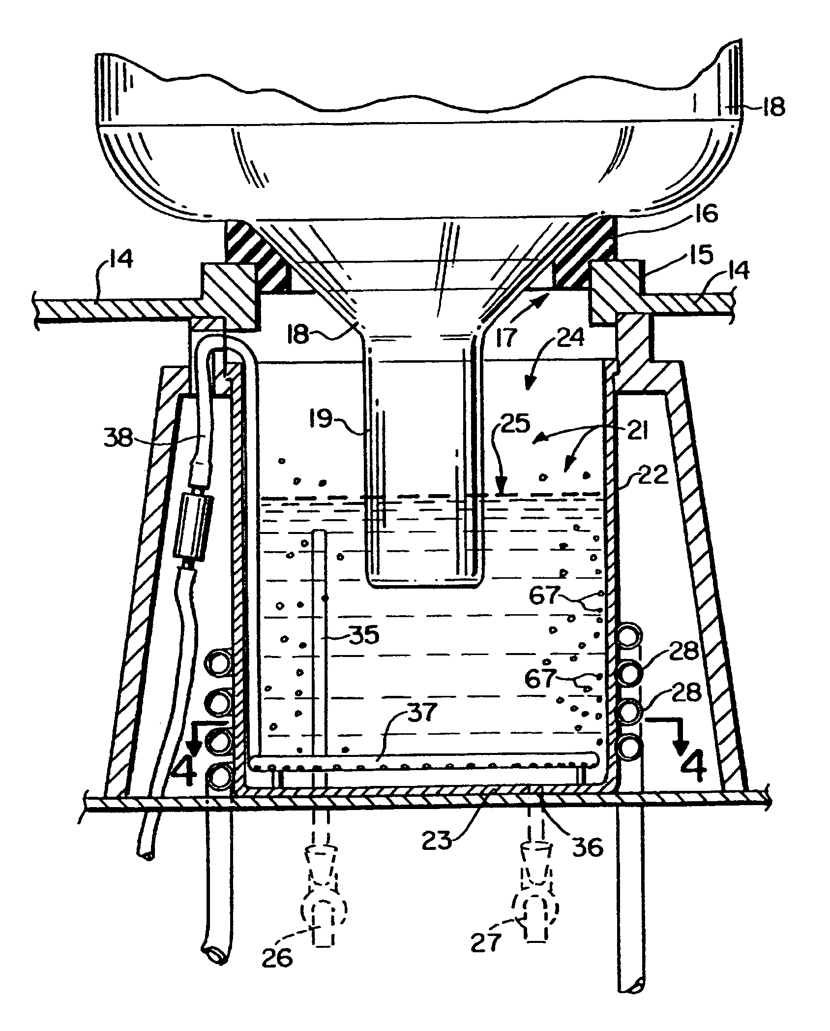
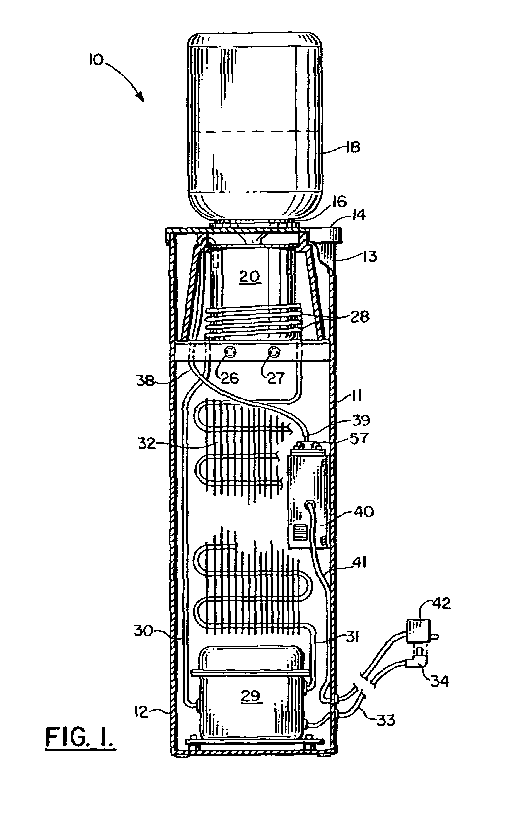
For inverted bottle type dispensers, in addition to the problem of an open top, the five gallon bottles are themselves a source of bacteria and germs.
Unfortunately, it is difficult to convince every person that handles these bottles to wash their hands frequently enough.
The cleansing of the reservoir in such a water dispenser is a time consuming project that is typically not performed at regular intervals.
The dispensing spigots that are provided on common cabinet type water dispensers can also be a source of contamination.
These spigots are typically manually operated and are therefore a source of contamination from the users that operate them.
Process ozone diffusion by bubble reactor method in small static volumes of water with abbreviated water columns to diffused ozone levels satisfactory to disinfect microorganisms in brief time periods can be difficult to achieve.
During the process of re-engineering equipment and reducing costs to fit small application needs, it was found that beyond basic principles, much of the available industrial technology proved of limited value.
Attempts at using prior art to address small applications have resulted in either failure to achieve minimal levels of sanitization or where success was achieved, systems that could not remain cost competitive.
Due to cost and space constraints small applications are limited to the use of small ambient air fed ozonators capable of generating less than 1% by weight ozone.
A large hurdle for small applications exhibiting static water volumes wi

Method used


Image

  • Method and apparatus for disinfecting a refrigerated water cooler reservoir
  • Method and apparatus for disinfecting a refrigerated water cooler reservoir
  • Method and apparatus for disinfecting a refrigerated water cooler reservoir

Examples


Example

[0160]FIGS. 15-27 show an alternate and second embodiment of the apparatus of the present invention. The second embodiment provides a manually operable dispensing spigot 100 with a special switch arrangement that automatically activates an ozone generator such as the generator shown and described with respect to the preferred embodiment of FIGS. 1-14. It should be understood that the alternate embodiment of FIGS. 15-18 includes the spigot 100 as well as a cabinet 11, reservoir 20, and the various flow lines of the embodiments of FIGS. 1-14. In other words, in the alternate embodiment, spigot 100 replaces spigots 26,27 of FIGS. 1-14. The spigot 100 triggers ozone generation and the transmission of ozone to the water contained within the reservoir. Ozone is also transmitted to a channel that connects the reservoir to the spigot, disinfecting water to be consumed.

[0161]In FIGS. 15-18, spigot 100 includes a spigot housing 101 to which is attached a handle 102 that enables a user to acti...


PUM


Abstract

A method and apparatus for providing sanitized water in a cabinet and spigot type bottled water dispenser features an ozone generating system to generate ozone for sanitizing the water. Ozone is generated and collected within an ozone generator housing. A blower transmits air to the ozone generator housing. The air carries the ozone that is generated through a flow line to an air diffuser that is positioned upstream of the spigot (or spigots) used to dispense water. In one embodiment, a valve that is activated on the spigot to dispense water also activates the blower and ozone generator. In other embodiments, a flow sensor activates the ozone generator and blower. Various spigot and flow sensor arrangements are disclosed as a part of the overall apparatus and method.

Description

CROSS-REFERENCE TO RELATED APPLICATIONS[0001]Priority of U.S. Provisional Patent Application No. 60 / 389,439, filed 18 Jun. 2002, hereby incorporated herein by reference, is hereby claimed. This is a continuation-in-part of U.S. patent application Ser. No. 10 / 173,133, filed 17 Jun. 2002 and of International Patent Application No. PCT / US02 / 19158, also filed 17 Jun. 2002, both incorporated herein by reference.[0002]Hereby incorporated herein by reference are U.S. patent application Ser. No. 09 / 996,328, filed 28 Nov. 2001; U.S. patent application Ser. No. 09 / 881,796 filed 15 Jun. 2001; U.S. patent application Ser. No. 09 / 954,849, filed 18 Sep. 2001; U.S. patent application Ser. No. 09 / 472,320, filed 23 Dec. 1999; and U.S. patent application Ser. No. 09 / 220,554, filed 23 Dec. 1998.STATEMENT REGARDING FEDERALLY SPONSORED RESEARCH OR DEVELOPMENT[0003]Not applicableREFERENCE TO A “MICROFICHE APPENDIX”[0004]There is no microfiche appendix, but see the text and drawings labeled as “Appendix A...

Claims


Application Information

Patent Timeline
IPC IPC(8): F25D3/00B67D7/06B67D7/58A61L2/20B67D1/00B67D3/00C02F1/78
CPCA61L2/202B67D3/0029C02F1/78C02F9/005B67D2210/00013B67D2210/00023C02F1/685C02F2201/782C02F2209/005C02F2209/40C02F9/20
Inventor SHELTON, JAMES J.
Owner S I P TECH L L C
Why Eureka
Try Eureka