Method and apparatus to maximize stored energy in UltraCapacitor Systems

a technology of ultracapacitor and storage energy, which is applied in the direction of hybrid vehicles, vehicle sub-unit features, electric devices, etc., can solve the problems of underutilization of the capability of the ucs, efficiency loss, and output voltage, so as to reduce the energy loss of the application system, reduce the mass of the ucs system, and high energy transfer efficiency

Inactive Publication Date: 2010-01-05
BARTILSON BRADLEY WAYNE
View PDF14 Cites 24 Cited by
  • Summary
  • Abstract
  • Description
  • Claims
  • Application Information

AI Technical Summary

Benefits of technology

[0011]Another object is to obtain high efficiency in energy transfer to and from the UCS.
[0012]Another object is to reduce energy losses of the application system by reducing the mass of the UCS system.
[0013]Another object is to reduce the complexity, cost, and component stress of the ESS control system.
[0014]Another object is to reduce energy losses by matching the energy charge / discharge capabilities of the UCS to that of the application system conditions, e.g. to readily transfer the burst of regenerative braking energy to the UCS with minimal loss.

Problems solved by technology

In order to fully-extract the energy from an Ultra-Capacitor System (UCS), they must undergo a large voltage decrease, causing system output voltage issues.
However, this methodology results in significant underutilization of the capability of the UCS (typically less than 50% as voltage input variations are limited to 2:1 for many devices).
The additions of banks (either battery or UC) bring increased switching components / complexity, efficiency loss, increased weight (reducing vehicle efficiency) and cost.
U.S. Pat. No. 6,265,851 describes an electric vehicle power system for a semiconductor wafer handling application, having ultracapacitors and batteries as parallel sources connected to a source-selecting switch and having said switch direct its output only to a DC-DC converter which serves the motor load, however, this incurs the converter losses when no conversion is necessary.
In the described topologies, all power is continuously directed through a power converter module, with inherent losses and limitations per device sizing.
This approach does not address the inefficient ultracapacitor capacity utilization issue, resulting in extensive burden / cycling of the engine and / or significant oversizing of the ultracapacitor bank.
While low in cost the use of the braking resistor diverts energy, thereby wasting said energy.

Method used


Image

  • Method and apparatus to maximize stored energy in UltraCapacitor Systems
  • Method and apparatus to maximize stored energy in UltraCapacitor Systems
  • Method and apparatus to maximize stored energy in UltraCapacitor Systems

Examples


Embodiment Construction

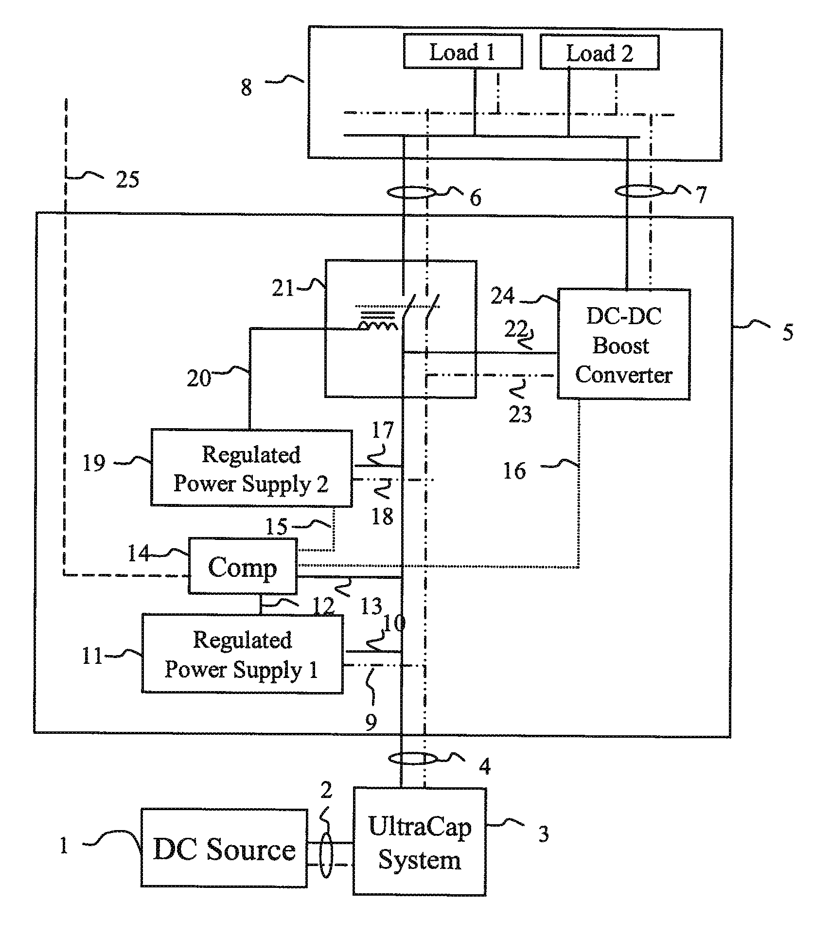
[0020]The present invention embodies an ESS system 5 comprising a UCS 3 (configuration of one or more “Ultra” or “Super” Capacitors) that receives supply energy from a DC source 1, stores such energy, supplies energy to a load or parallel configuration of DC loads, and may receive and store energy returning from the former loads.

[0021]FIG. 1 illustrates the schematic of the ESS 5. Therein a DC Source 1 renders power as demanded by a higher-level application control system (a typical control system operates the DC source in response to load or bus or other application system conditions). Energy from said DC Source 1 is fed to UCS 3 via electrical connectors 2. UCS 3 contains an application-defined capacity and configuration of UCs. UCS energy is fed to the ESS 5 Control System via connection bus 4. The Comparator Circuit 14 monitors the high voltage side of the feed bus 4 via connector 13. When the feed bus 4 high voltage falls beneath a threshold value the Comparator Circuit 14 rele...


PUM


Abstract

The control system for an UltraCapacitor (or “SuperCapacitor) based energy storage system consists of a relay switch, a voltage up-converting device (e.g. DC-DC converter), regulated power supplies and a comparator circuit. The comparator circuit compares the storage system output voltage with a reference voltage, causing the storage system output to be diverted through a voltage up-converting device when the said voltage has declined to a threshold value (typically set by the load requirements). Wide-input range power supplies enable consistent operation of the circuit as the UltraCapacitor system output bus voltage declines. The wide-range of input allowed by the up-converting device enables the continuance of power drain from the UltraCapacitors, i.e. more efficient use of available storage capacity, while maintaining the required output voltage to the load. Efficiency is increased by direct connection of the UltaCapacitor system to the load bus until its voltage falls below stated threshold. In the case of a given 48 VDC system electric motor application, 500% more energy is extracted from the UltraCapacitor system with the stated control system than would be permitted by the load voltage requirements without such system.

Description

BACKGROUND OF THE INVENTION[0001]The present invention relates to an apparatus and method to extract a larger portion of the available energy capacity of “Ultra-Capacitor” (or “Super-Capacitor”) energy storage systems (ESS).DESCRIPTION OF RELEVANT ART[0002]Newly-developed Ultra-Capacitor (UC) technology, enables extreme advances in the rate of serving large amounts of charge to and from an energy storage system, e.g. discharging at 1000 A for 30 seconds. UCs exhibit high charge and discharge efficiency (˜98%), and a significant advantage in applications where energy efficiency improvement is desired. UCs provide a large scale increase in power density (10 kW / kg) over the most advanced batteries today (1 kW / kg).[0003]In order to fully-extract the energy from an Ultra-Capacitor System (UCS), they must undergo a large voltage decrease, causing system output voltage issues. Additionally, UCs exhibit lower energy density (1-20 W-hr / kg) than batteries (50-100 W-hr / kg). The use of UCs in c...

Claims


Application Information

Patent Timeline
Patent Type & Authority Patents(United States)
IPC IPC(8): H02J7/00B60L1/00
CPCB60K6/28B60K6/46B60W10/08B60W10/26B60W10/24B60W20/13Y02T10/6217Y02T10/6278B60Y2400/114B60W20/00Y02T10/62
Inventor BARTILSON, BRADLEY WAYNE
Owner BARTILSON BRADLEY WAYNE
Why Eureka
Try Eureka