Method and arrangement for processing nitrogen-concentrated effluents in a sequential fractionated cycle biological reactor

a biological reactor and fractionation cycle technology, applied in biochemistry equipment, water/sludge/sewage treatment, biochemistry apparatus and processes, etc., can solve the problems of increasing control difficulties of many pollutant processing installations, ammonia liable to cause environmental damage, and expensive revamping of existing processing stations, so as to improve the self-regulation of the ph of the medium

Active Publication Date: 2010-01-12
ONDEO DEGREMONT INC +1
View PDF6 Cites 11 Cited by
  • Summary
  • Abstract
  • Description
  • Claims
  • Application Information

AI Technical Summary

Benefits of technology

[0036]The invention allows better self-regulation of the pH of the medium

Problems solved by technology

Many pollutant processing installations are faced with growing difficulties associated with the control and the processing of their nitrogen-containing, chiefly ammoniacal releases, in the host environments.
The ammonia is liable to cause environmental damage such as the oxygen depletion of aquatic environments, toxicity to fish, or eutrophization processes.
To limit these impacts, the regulations impose increasingly stringent release limits, which often entail the costly revamping of existing processing stations.
For releases such as anaerobic digester supernatants, gas processing condensates and landfill leachates

Method used


Image

  • Method and arrangement for processing nitrogen-concentrated effluents in a sequential fractionated cycle biological reactor
  • Method and arrangement for processing nitrogen-concentrated effluents in a sequential fractionated cycle biological reactor
  • Method and arrangement for processing nitrogen-concentrated effluents in a sequential fractionated cycle biological reactor

Examples


example

[0099]The average nitrogenous feed of a digested sludge centrifugation supernatant is 150 kg N / d for an average concentration of 600 mg N—NH4+ / l, but varies between 400 and 1000 N—NH4+ / l. It is also considered that the feed is stopped for three days after a centrifuge breakdown around the twentieth day giving rise to a zero flow (FIG. 6).

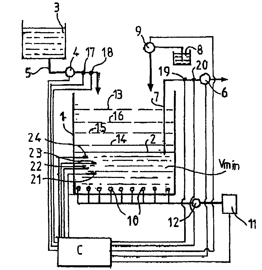
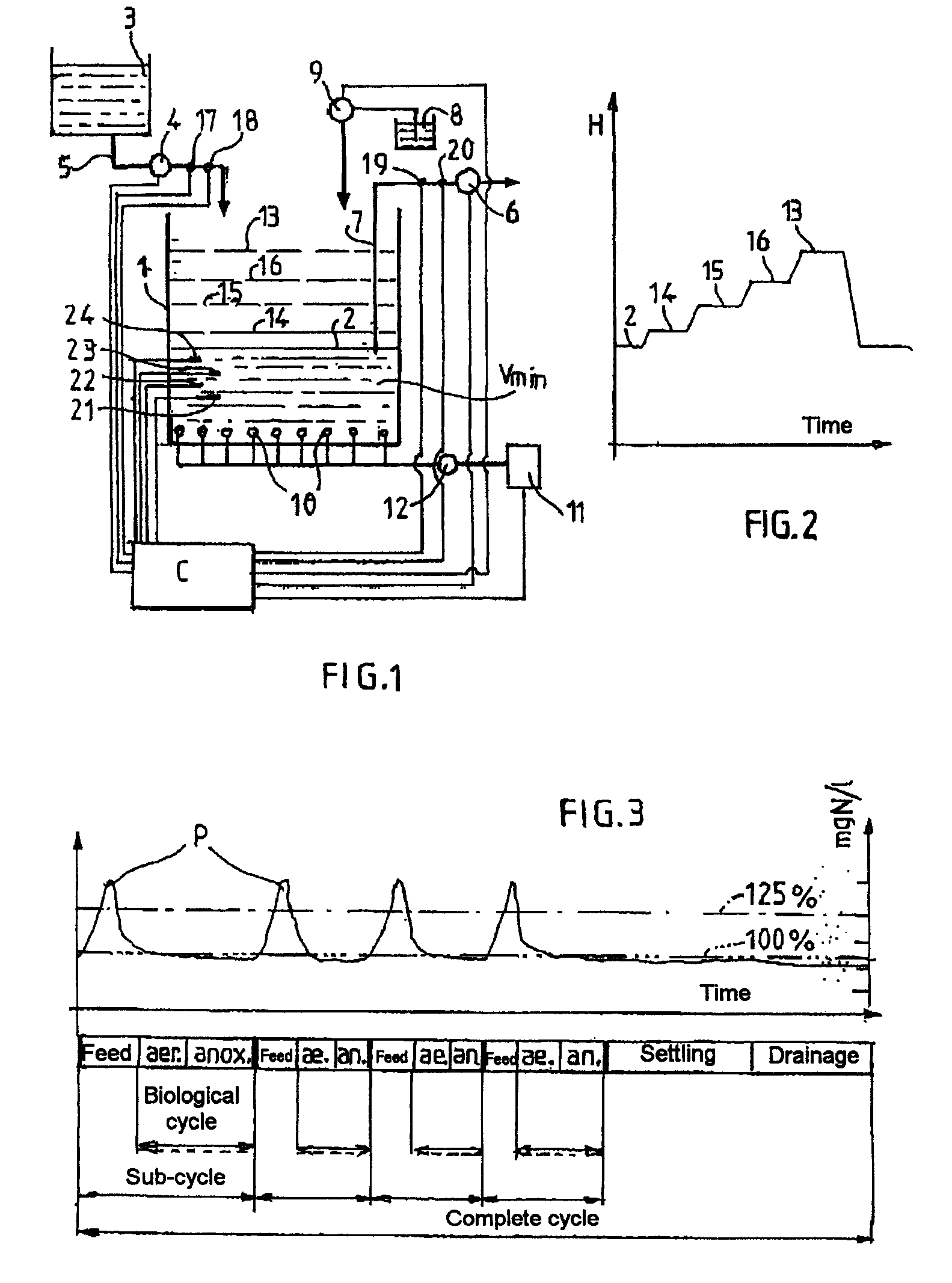
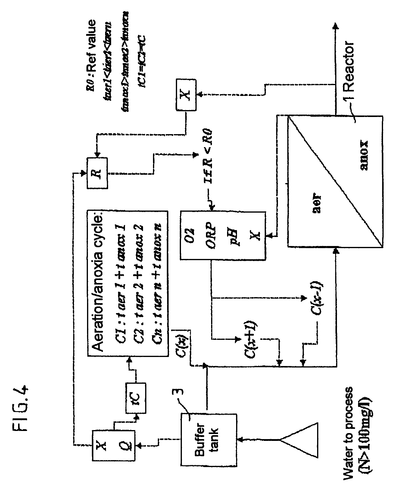
[0100]This nitrogenous feed is processed in a sequential biological reactor (SBR) with a capacity of 450 m3 and a liquid height of between 3 and 4 m, in three complete cycles of 8 h / d. A fraction of the minimum feed (Nalimmin) into 4 phases was calculated with the following assumptions: [NH4+]eff=50 mg N / l, [NH3]inhib=10 mg N—NH3 / l, pH=8.3, T=25° C. The resulting biological time tC, of 90 minutes, was consistent with the minimum fixed for the system. Four “feed / aeration / anoxia” sub-cycles were therefore applied before the settling and withdrawal steps in order to avoid inhibition by the ammoniacal concentration at the highest pH, so as to apply a su...


PUM

PropertyMeasurementUnit
Temperatureaaaaaaaaaa
Fractionaaaaaaaaaa

Abstract

The invention relates to a method for processing nitrogen-concentrated effluents by ammonia oxidation into nitrites followed by nitrite denitritation in a gaseous nitrogen in a sequential biological reactor (1) consisting in pouring a processable effluent volume in to the reactor by successive volume fractions, in dividing the entire processing cycle into successive sub cycles, wherein each sub-cycle comprises a feeding phase, an aeration phase for nitrification and an anoxia phase along which a carbon-containing source is introduced into the reactor for converting nitrites into nitrogen. The inventive method also consists in evaluating a nitrogenous volume charge in the effluent to be processed, mainly by measuring the effluent conductivity (X) and the flow rate (Q) and in determining the number of feeding phases of the entire cycle according to nitrogenous charge and to a minimum volume of liquid in the reactor in such a way that an injected nitrogen concentration is diluted in the liquid volume, wherein the volume phase nitrogenous charge is however sufficient for producing a single shot or peak of the ammonia charge favourable for a nitrating biomass formation in the reactor.

Description

CROSS REFERENCE TO RELATED APPLICATIONS[0001]This application is a National Phase filing under 35 U.S.C. 371 of PCT / FR2006 / 001841 filed Jul. 27, 2006, which claims priority to Patent Application No. 0508201, filed in France on Aug. 1, 2005. The entire contents of each of the above-applications are incorporated herein by reference.BACKGROUND OF THE INVENTION[0002]The invention relates to a method for processing nitrogen-concentrated effluents, by oxidizing ammonium to nitrites followed by a denitration of the nitrites to nitrogen gas in a sequential biological reactor in which the reaction phases are fractionated, a method whereby an inflow volume to be processed is poured into the reactor containing nitrifying bacteria, the operating conditions being provided to privilege the action of the nitriting bacteria and to inhibit the action of the nitrating bacteria to the maximum, comprising processing cycles with at least one aeration phase to cause the nitrification, followed by a phase...

Claims


Application Information

Patent Timeline
IPC IPC(8): C02F3/30C02F3/12G05B15/00
CPCC02F1/008C02F3/1263C02F3/30Y02W10/15C02F2103/06C02F2103/18Y10S210/903C02F2101/16Y02W10/10
Inventor MARTIN, SAMUELGONZALEZ OSPINA, ADRIANA
Owner ONDEO DEGREMONT INC
Why Eureka
Try Eureka