Eureka AIR delivers breakthrough ideas for toughest innovation challenges, trusted by R&D personnel around the world.

Method of forming thin film

a thin film and film technology, applied in the direction of organic chemistry, transportation and packaging, synthetic resin layered products, etc., can solve the problems of no process for efficiently preparing, wide weight distribution of obtained polymers, and purity of crystal form i

Inactive Publication Date: 2010-02-02
DAIKIN IND LTD
View PDF14 Cites 7 Cited by
  • Summary
  • Abstract
  • Description
  • Claims
  • Application Information

AI Technical Summary

Benefits of technology

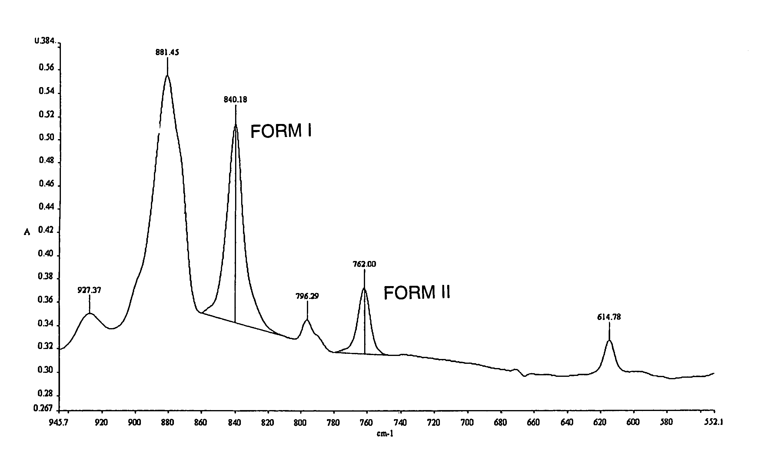
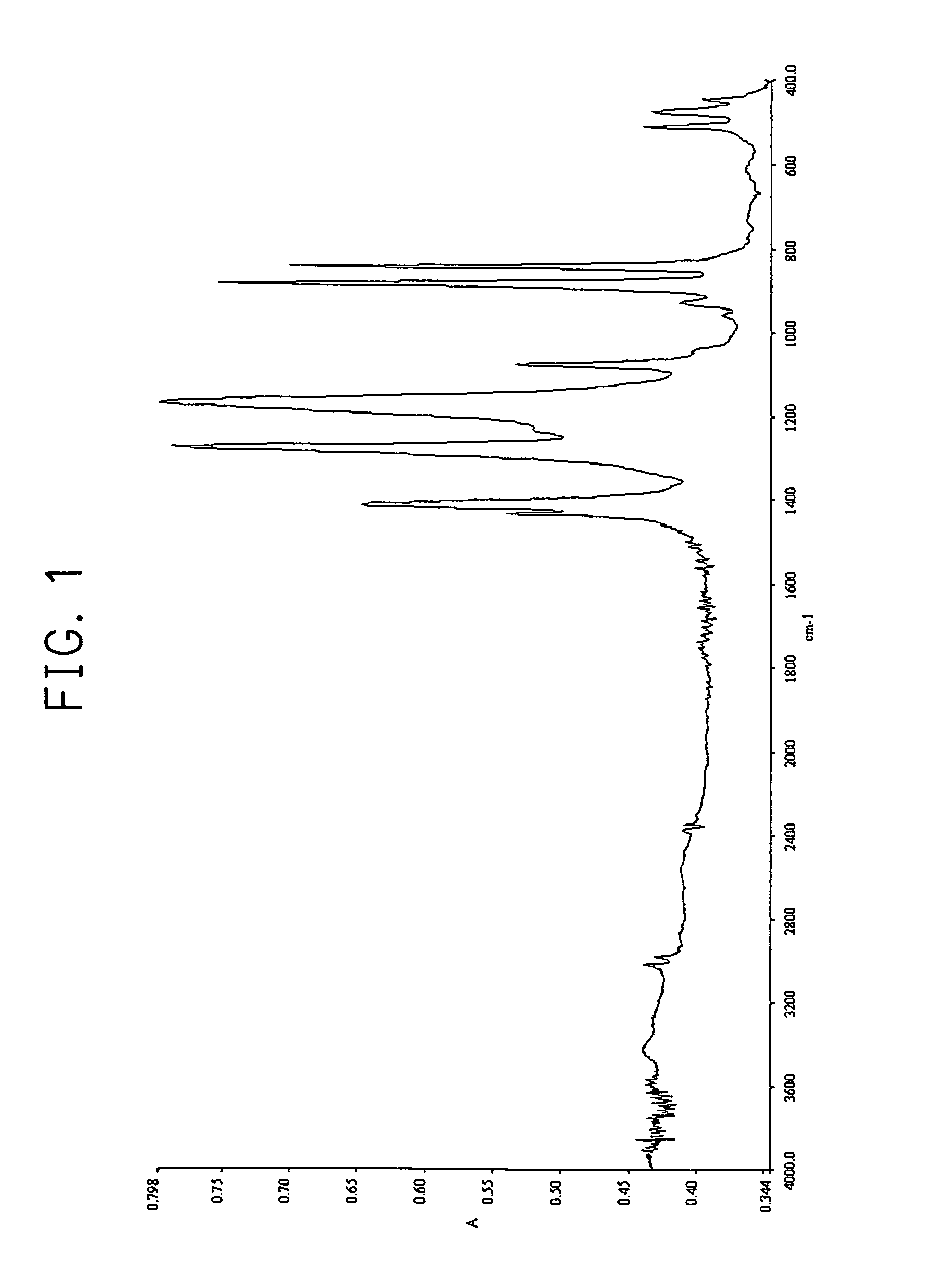
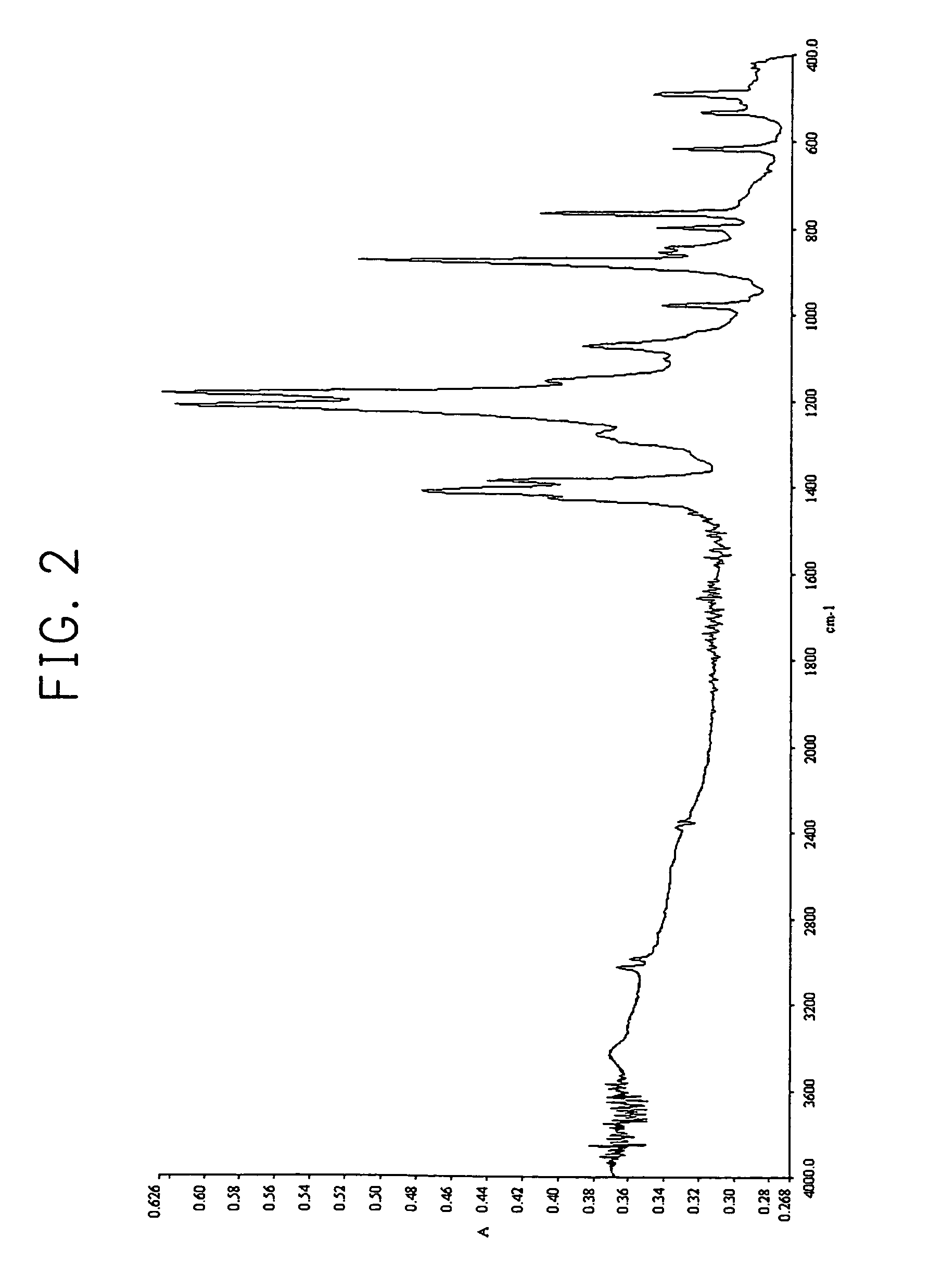
[0016]The first object of the present invention is to provide a method of forming a thin film of vinylidene fluoride homopolymer having crystal form I which is applicable to various substrates in a relatively easy manner (coating conditions, application method, etc.).
[0017]The second object of the present invention is to provide a process for preparing a vinylidene fluoride homopolymer having crystal form I efficiently at high purity.

Problems solved by technology

However there is a problem that a molecular weight distribution of the obtained polymer becomes wide, and a purity of crystal form I (β-form) is lowered like the above-mentioned preparation processes.
However all of those preparation processes are intended to prepare vinylidene fluoride copolymers (copolymer oligomers), and studies on vinylidene fluoride homopolymers (homopolymer oligomers) having crystallinity have not been made.
Furthermore there are disclosed no processes for efficiently preparing, at high purity, vinylidene fluoride homopolymers having crystal form I (β-form) which can exhibit ferroelectric characteristics.

Method used


Image

  • Method of forming thin film
  • Method of forming thin film
  • Method of forming thin film

Examples


preparation example 1

Synthesis of CF3(VdF)nI

(1-1) Synthesis of CF3(VdF)8.1I (n=8.1)

[0210]Into a 300 ml stainless steel autoclave equipped with a valve, pressure gauge and thermometer was poured 50 g of HCFC-225, and while cooling with a dry ice / methanol solution, 0.78 g of di-n-propylperoxy dicarbonate (50% by weight of methanol solution) was added and the inside of a system was sufficiently replaced with nitrogen gas. After the inside pressure of the system was reduced, 5.2 g of CF3I was introduced through the valve, and after heating of the system up to 45° C., VdF was introduced until the inside pressure of the system became 0.8 MPaG. While maintaining the inside pressure and temperature of the system at 0.8 MPaG and 45° C., respectively, VdF was continuously introduced and 9-hour reaction was carried out.

[0211]After completion of the reaction, the inside temperature of the system was decreased to 25° C. and the unreacted substances (VdF and CF3I) were released. Then the precipitated solid reaction p...

preparation example 2

Synthesis of CF3CF2(VdF)nI

(2-1) Synthesis of CF3CF2(VdF)10.9I (n=10.9)

[0238]Into a 300 ml stainless steel autoclave equipped with a valve, pressure gauge and thermometer was poured 50 g of HCFC-225, and while cooling with a dry ice / methanol solution, 0.08 g of di-n-propylperoxy dicarbonate (50% by weight of methanol solution) was added and the inside of a system was sufficiently replaced with nitrogen gas. After the inside pressure of the system was reduced, 1.96 g of CF3CF2I was introduced through the valve, and after heating of the system up to 45° C., VdF was introduced until the inside pressure of the system became 0.8 MPaG. While maintaining the inside pressure and temperature of the system at 0.8 MPaG and 45° C., respectively, VdF was continuously introduced and 9-hour reaction was carried out.

[0239]After completion of the reaction, the inside temperature of the system was decreased to 25° C. and the unreacted substances (VdF and CF3CF2I) were released. Then the precipitated s...

preparation example 3

Synthesis of I(VdF)nC4F8(VdF)mI

(3-1) Synthesis of I(VdF)n(CF2CF2)2(VdF)mI (n+m=8.7)

[0242]Into a 300 ml stainless steel autoclave equipped with a valve, pressure gauge and thermometer was poured 50 g of HCFC-225, and while cooling with a dry ice / methanol solution, 0.27 g of di-n-propylperoxy dicarbonate (50% by weight of methanol solution) was added and the inside of a system was sufficiently replaced with nitrogen gas. After the inside pressure of the system was reduced, 1.96 g of I(CF2CF2)2I was introduced through the valve, and after heating of the system up to 45° C., VdF was introduced until the inside pressure of the system became 0.8 MPaG. While maintaining the inside pressure and temperature of the system at 0.8 MPaG and 45° C., respectively, VdF was continuously introduced and 9-hour reaction was carried out.

[0243]After completion of the reaction, the inside temperature of the system was decreased to 25° C. and the unreacted substances (VdF and I(CF2CF2)2I) were released. Th...


PUM

PropertyMeasurementUnit
temperatureaaaaaaaaaa
thicknessaaaaaaaaaa

Abstract

There is provided a method of forming a thin film of vinylidene fluoride homopolymer having crystal form I which is applicable to various substrates in relatively easy way (coating conditions, application method, etc.), a process for preparing a vinylidene fluoride homopolymer having crystal form I efficiently at high purity, and novel vinylidene fluoride homopolymers which can give a thin film being excellent in ferroelectricity. The method of forming a thin film of vinylidene fluoride homopolymer comprises (i) a step for preparing a green powder product of vinylidene fluoride homopolymer comprising crystal form I alone or as main component by subjecting vinylidene fluoride to radical polymerization in the presence of a bromine compound or iodine compound having 1 to 20 carbon atoms which contains at least one moiety represented by —CRf1Rf2X1, wherein X1 is iodine atom or bromine atom; Rf1 and Rf2 are the same or different and each is selected from fluorine atom or perfluoroalkyl groups having 1 to 5 carbon atoms and (ii) a step for forming a thin film on a substrate surface by using vinylidene fluoride homopolymer which comprises crystal form I alone or as main component and is obtained from the green powder product of vinylidene fluoride homopolymer comprising crystal form I alone or as main component.

Description

CROSS-REFERENCE TO RELATED APPLICATION[0001]This is a continuation-in-part of PCT international application No. PCT / JP2004 / 004028 filed on Mar. 24, 2004, incorporated herein by reference.BACKGROUND OF THE INVENTION[0002]The present invention relates to a method of forming a thin film of vinylidene fluoride homopolymer having crystal form I. The present invention also relates to a process for preparing a vinylidene fluoride homopolymer having crystal form I as main component which is used for forming the thin film. The present invention further relates to a novel vinylidene fluoride homopolymer.[0003]Polymer type ferroelectric materials have advantages such as flexibility, light-weight, good processability and low price as compared with inorganic ferroelectric materials such as ceramics. There are known, as represented examples thereof, vinylidene fluoride polymers such as polyvinylidene fluoride (PVdF) and vinylidene fluoride / trifluoroethylene (VdF / TrFE) copolymer.[0004]With respect...

Claims


Application Information

Patent Timeline
Patent Type & Authority Patents(United States)
IPC IPC(8): C08F14/18B32B27/30B05D7/24C08F2/38C08F14/22C08F114/22C09D127/16C23C14/12
CPCC07C21/18C08F114/22Y10T428/31544Y10T428/3154
Inventor ARAKI, TAKAYUKIKODANI, TETSUHIRO
Owner DAIKIN IND LTD
Why Eureka
Eureka Blog
Learn More