Double ducted hovering air-vehicle

a technology of air-vehicle and ducted fan, which is applied in the direction of vertical landing/take-off aircraft, transportation and packaging, and lighter-than-air aircraft, etc. it can solve the problems of reduced payload and endurance, increased aero-acoustic noise signature of ducted fan solutions, and increased weight of back packing ability, etc., to achieve increased endurance, increase lift performance, and increase payload

Inactive Publication Date: 2010-02-09
HONEYWELL INT INC
View PDF38 Cites 63 Cited by
  • Summary
  • Abstract
  • Description
  • Claims
  • Application Information

AI Technical Summary

Benefits of technology

[0025]A primary advantage of the present invention is that it provides an increased lift performance for a ducted fan vehicle with transport container constraints supporting larger payloads.
[0026]Another advantage of the present invention is that it provides increased endurance from aerodynamic efficiencies and increased fuel loads for a ducted fan vehicle-in small transport container.
[0027]Another advantage of the present invention is that it provides a reduced aero-acoustic signature through elimination of inflow disturbance sources from no engine or engine mount in front of the fan.
[0028]Another advantage of the present invention is that it provides for quick assembly / disassembly through use of splined shafts and dove-tail structural connections.
[0029]Another advantage of the present invention is that it provides structural solidarity over cantilevered pods.
[0030]Another advantage of the present invention is that the tail cones reduce the contraction ratio as well as provide passive stability.

Problems solved by technology

The problem is that the physics of the various parameters of; packing size weight and volume, endurance, acoustics, and fuel consumption all play against each other to make an optimum system that is humanly portable by the average soldier.
Human back packing ability imposes additional weight, container constraint sizing constraints and plays against performance and set up times with a resulting reduced payload and endurance.
These single ducted fan solutions also suffer from increased aero-acoustic noise signatures because of these same airflow disturbances.
The trailing attitude control vanes impact not only the acoustic noise signature but contribute to added drag and do nothing to counteract the natural outflow contraction ratio.
Payload modularity is severely limited for axial locations with payloads of varying mass distributions as small shifts of the cg require control stabilization changes and can very quickly make the vehicle uncontrollable.
These vehicles are statically unstable and even though passive stability is desired it is not attained.
Compounding the cg management problem is the electrical wiring between pods and control effectors.
There are no convenient wire routing channels between payloads and avionics located around the exterior of the duct or axially above or below the engine.
The compromises will usually impact weight, efficiency, and limit payload modularity.
Minimum gap between the fan blades and the duct is desired for greatest efficiency but is limited by the engine vibration and structural bending of the engine mound and duct.
The duct attachment point is also a high structural failure point.
Sensor integrity is compromised when blurred by vibration from payload pods mounted cantilevered around the duct and in front of or below the engine due to natural body bending modes.
These effects add up to more exotic materials and weight to manage the undesirable effects.
Endurance and / or persistence of the vehicle mission are impacted with the limited fuel carrying capacities when the only location for fuel is limited to the interior of the duct.
Sensor visibility is severely restricted by either axially in-line or laterally duct mounted pods.
Laterally mounted side pod sensors have good visibility forward and down in hover and forward flight, but are limited to side viewing.
Maintenance, repair, and replacement of components is limited because of the complexity associated with component assembly.
With all these issues previous solutions have focused only on individual elements of the problem or some combination of the problems but have failed to provide a solution that addresses the complete physics of a fieldable system.

Method used


Image

  • Double ducted hovering air-vehicle
  • Double ducted hovering air-vehicle
  • Double ducted hovering air-vehicle

Examples


Embodiment Construction

)

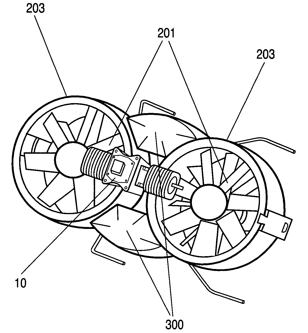
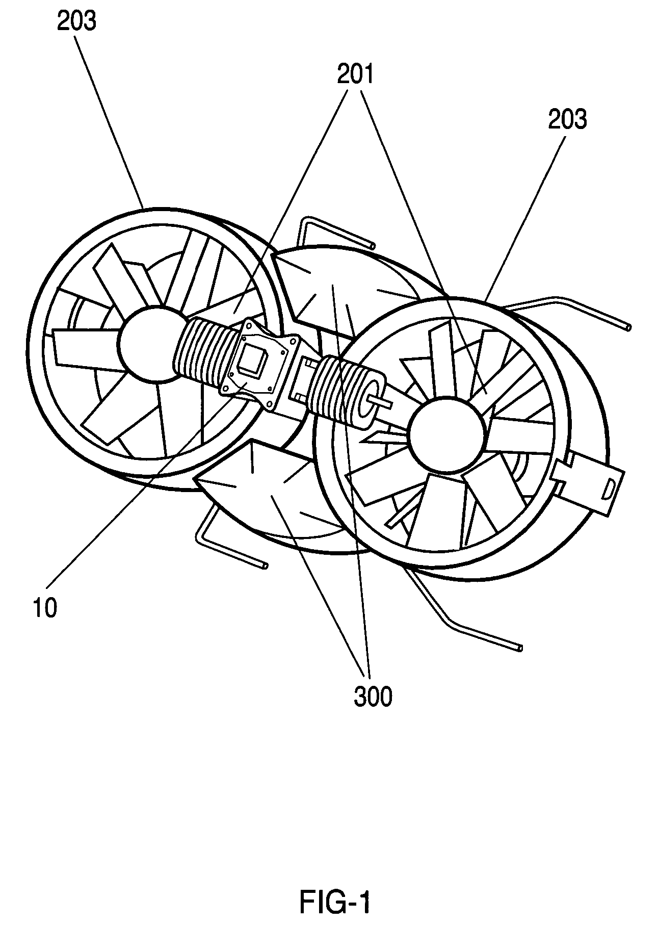
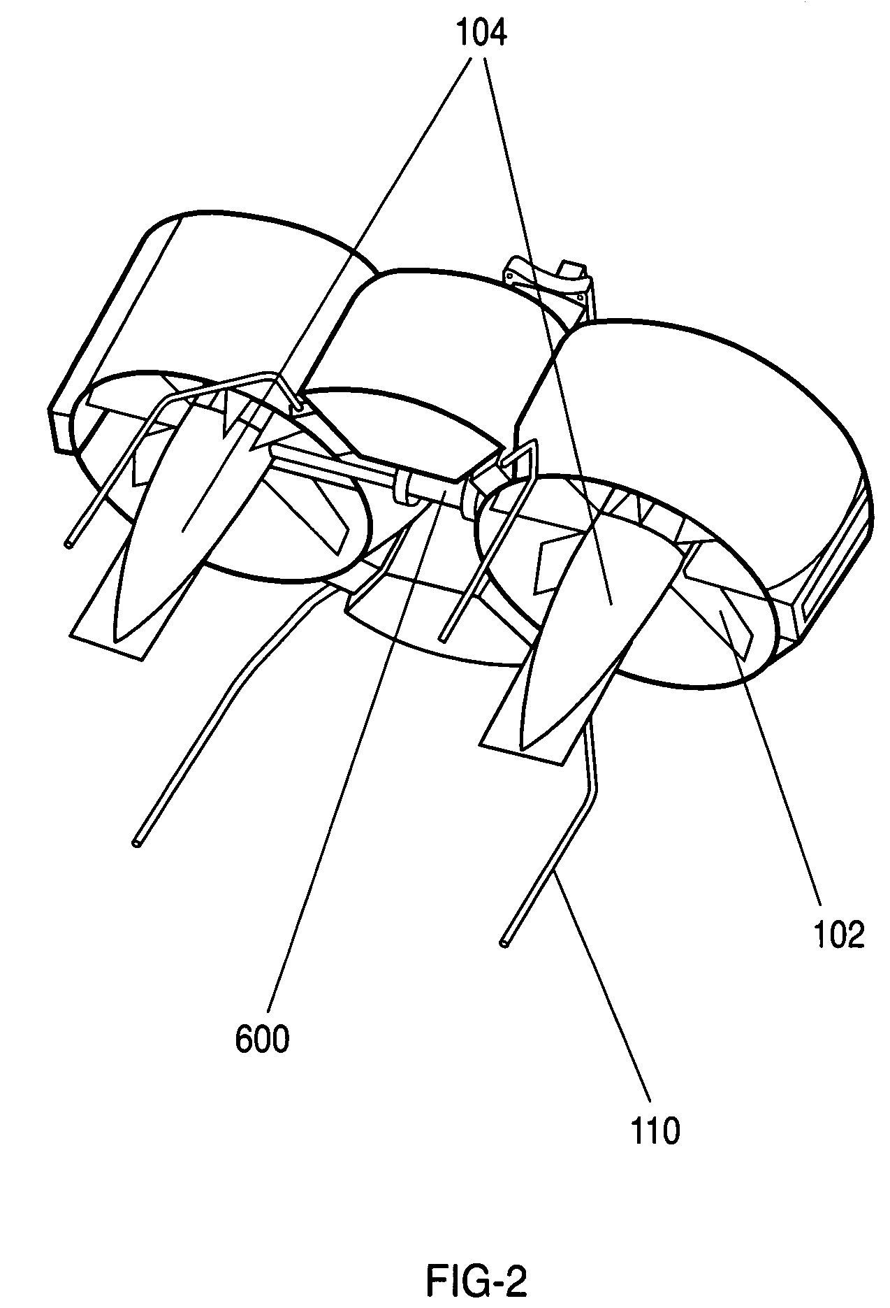
[0053]Aspects of the present invention provide a system and method for construction of a double-ducted hovering air-vehicle. In the carrying of payloads the present invention has enhanced aerodynamic and acoustic performance. It also provides payload and transport packing flexibility.

[0054]Although the following disclosure will make reference to a double ducted hovering air-vehicle it should be appreciated that the present invention may have a broader applicability in the field of air-borne vehicles. Particular configurations discussed in examples can be varied and are merely cited to illustrate an embodiment of the present invention and are not intended to limit the scope of the invention.

[0055]Referring to FIG. 1 and FIG. 2, the present invention teaches the construction of a double-ducted air-vehicle assembly consisting of two ducted fan assemblies 203, two avionics / payload pods 300, a reciprocating or turbine engine 10, a differential 600, tail cones 104, and landing gear 110. ...


PUM


Abstract

A dual ducted fan arrangement in which the duct components, engine, and avionics / payload pods are capable of being quickly disassembled to fit within common backpacking systems. Each duct is identical in fan, stator, and control vane design. Assembly connections between ducted fans and electronic modules are also identical. An engine or APU drives the dual ducted fans through a splined shaft to a differential or through electric motors. Energy is transferred to the ducted fans by a single gear mounted to the stator hub. Relative speeds of the individual ducted fans are controlled through separate frictional or generator load control braking mechanisms on each of the splined shafts between the differential and ducted fans. In the electric motor case relative speed is through electronic speed control. The fans are counter rotating for torque balancing. The electronic module locations are vertically variable for longitudinal center of gravity for variations in payloads.

Description

CROSS-REFERENCE TO RELATED APPLICATIONS[0001]This application is based on U.S. Provisional Application Ser. No. 60 / 656,811 entitled “Double Ducted Hovering Air-Vehicle”, filed on Feb. 25, 2005, the teachings of which are incorporated herein by reference.STATEMENT REGARDING FEDERALLY SPONSORED RESEARCH OR DEVELOPMENT[0002]This invention was made with Government support under Agreement No. MDA972-01-9-0018 awarded by the Defense Advanced Research Projects Agency (DARPA). The Government has certain rights in this invention.BACKGROUND OF THE INVENTION[0003]1. Field of the Invention (Technical Field)[0004]The present invention relates generally to the field of hovering and vertical take off and landing vehicles. More specifically, the present invention relates to air-vehicles with ducted fans as the propulsion system.[0005]2. Background Art[0006]Ducted fan configurations are known for their superior aerodynamic performance over non-ducted fans and several implementations of ducted fan ho...

Claims


Application Information

Patent Timeline
Patent Type & Authority Patents(United States)
IPC IPC(8): B64C27/08
CPCB64C27/20B64C29/0016B64C39/024B64C2201/027B64C2201/088B64C2201/201B64C2201/108B64C2201/128B64C2201/162B64C2201/165B64C2201/102B64U10/13B64U70/80B64U30/12B64U30/20B64U2101/60B64U50/14B64U50/13B64U80/70B64C29/00B64C39/02
Inventor GOOSSEN, EMRAY R.
Owner HONEYWELL INT INC
Why Eureka
Try Eureka