Ceiling microphone assembly

a microphone and floor technology, applied in the direction of electrical transducers, electrical transducers, transducer types, etc., can solve the problems of poor signal/noise ratio, cluttered room, and poor quality of audio or video conferencing applications, and achieve the best signal/noise ratio and the capacity of microphones can grow.

Active Publication Date: 2010-02-09
HEWLETT PACKARD DEV CO LP
View PDF8 Cites 38 Cited by
  • Summary
  • Abstract
  • Description
  • Claims
  • Application Information

AI Technical Summary

Benefits of technology

[0011]The current invention uses multiple unidirectional microphone elements in a microphone assembly. The microphone assembly is installed overhead, generally above all the desired sound sources. The signals from these multiple microphone elements are fed into a microphone steering processor which mixes and gates the signals to ensure the best signal / noise ratio. The steering processor may also track the sound source dynamically when such tracking (source locating) is desired. The resulting audio signal from the steering processor may be further processed, such as echo canceling, noise reduction and automatic gain control. The microphones of the current invention can cover a large conference room. They are also scalable, that is, when the conference room grows, capacities of the microphones can grow accordingly by adding more microphones.

Problems solved by technology

Any one of the four types of microphones identified above has various disadvantages in audio systems, especially in audio conferencing and video conferencing applications.
For example, an omni-direction microphone, which gathers sound from all directions equally, can be used in recording studios where the noise and reverberation level can be made to low, but gives poor quality in audio or video conferencing applications, because of its inability to reject reverberation and noise in a typical untreated room environment.
But this type of arrangement complicates the conference room and makes the room cluttered.
Although it is generally accepted that one may have to hold a microphone while giving a lecture in a large auditorium, it is still unnatural and inconvenient.
In a conference situation, it is even worse.

Method used


Image

  • Ceiling microphone assembly
  • Ceiling microphone assembly
  • Ceiling microphone assembly

Examples


Embodiment Construction

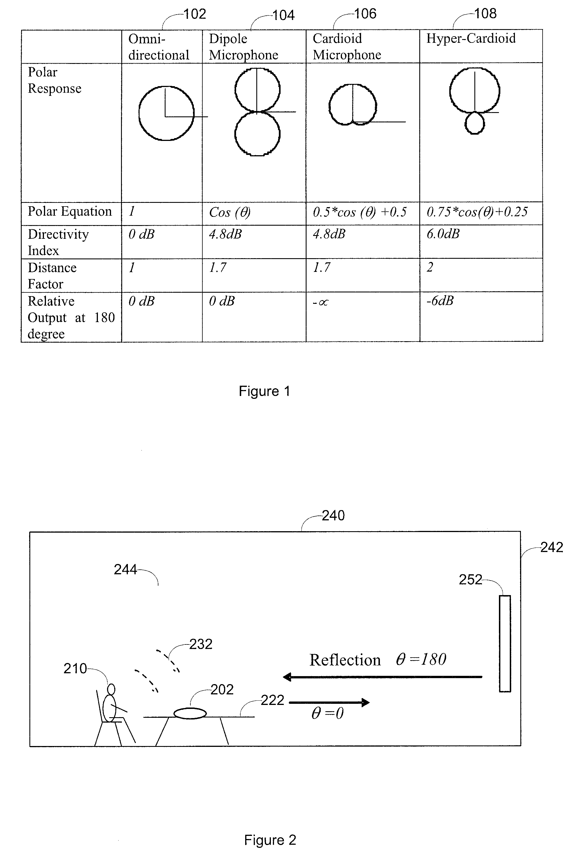
[0022]FIG. 2 shows a typical conference room arrangement 244. A conference participant 210 sits at a conference table 222, facing a video monitor 252 at a side wall 242. A microphone 202 (or several microphone elements in a speakerphone such as a Polycom SoundStation VTX-1000 speakerphone) may be placed on the conference table 222. Speech 232 may propagate within the conference room and may be reflected by walls, e.g. 242, and ceiling 240. The reflected sound waves, which may also be referred to as room reverberation, are typically undesired and should be rejected by the microphone if possible. It can be done when a cardioid microphone is used. The cardioid microphone only accepts sound waves in one direction. The reflected sound waves, which are in the opposite direction, are rejected. This way, the cardioid microphone can reject the unwanted first-stage reverberations from the room, leading to an improvement of the direct to reverb ratio.

[0023]Since a single cardioid microphone el...


PUM


Abstract

An overhead microphone assembly using multiple unidirectional microphone elements. The microphone assembly is installed overhead, generally above all the desired sound sources and below the undesired sound sources. The signals from these multiple microphone elements are fed into a microphone steering processor which can mix and gate the signals to ensure the best signal / noise ratio. The steering processor may also track the sound source dynamically when such tracking (source locating) is desired. The resulting audio signal from the steering processor may be further processed, such as echo canceling, noise reduction and automatic gain control.

Description

RELATED APPLICATIONS[0001]This application claims priority from U.S. provisional patent application, No. 60 / 621,743, filed on Oct. 25, 2004 with the same title and assigned to the same assignee, which is incorporated herein by reference.BACKGROUND OF THE INVENTION[0002]1. Field of the Invention[0003]This invention relates generally to microphone assembly in a system which needs to convert sound waves to electrical signals.[0004]2. Description of the Related Art[0005]A microphone is a basic and essential element in any audio systems. There are many types of microphones in use currently. Generally, they are classified in four categories as listed in FIG. 1. The first one is an omni-directional microphone 102. It has a uniform polar response, i.e., the sound waves from any directions can be accepted and an electrical signal is generated with the same gain. A second type of microphone, a dipole microphone 104, can respond to sound waves mainly from two opposite directions. Sound waves c...

Claims


Application Information

Patent Timeline
Patent Type & Authority Patents(United States)
IPC IPC(8): H04R9/08
CPCH04R1/025H04R1/406H04R3/005
Inventor RODMAN, JEFFREYCHU, PETERNIMRI, ALAINSCHAEFER, STEPHENSEXTON, MARTIN G.
Owner HEWLETT PACKARD DEV CO LP
Why Eureka
Try Eureka