Multipoint ignition engine
a multi-point ignition and engine technology, applied in the direction of spark plugs, machines/engines, mechanical equipment, etc., can solve the problems of reducing the propagation speed and the inability to achieve the expected rapid combustion, and achieve the effect of rapid burning and improving the output and fuel efficiency of the engin
- Summary
- Abstract
- Description
- Claims
- Application Information
AI Technical Summary
Benefits of technology
Problems solved by technology
Method used
Image
Examples
first embodiment
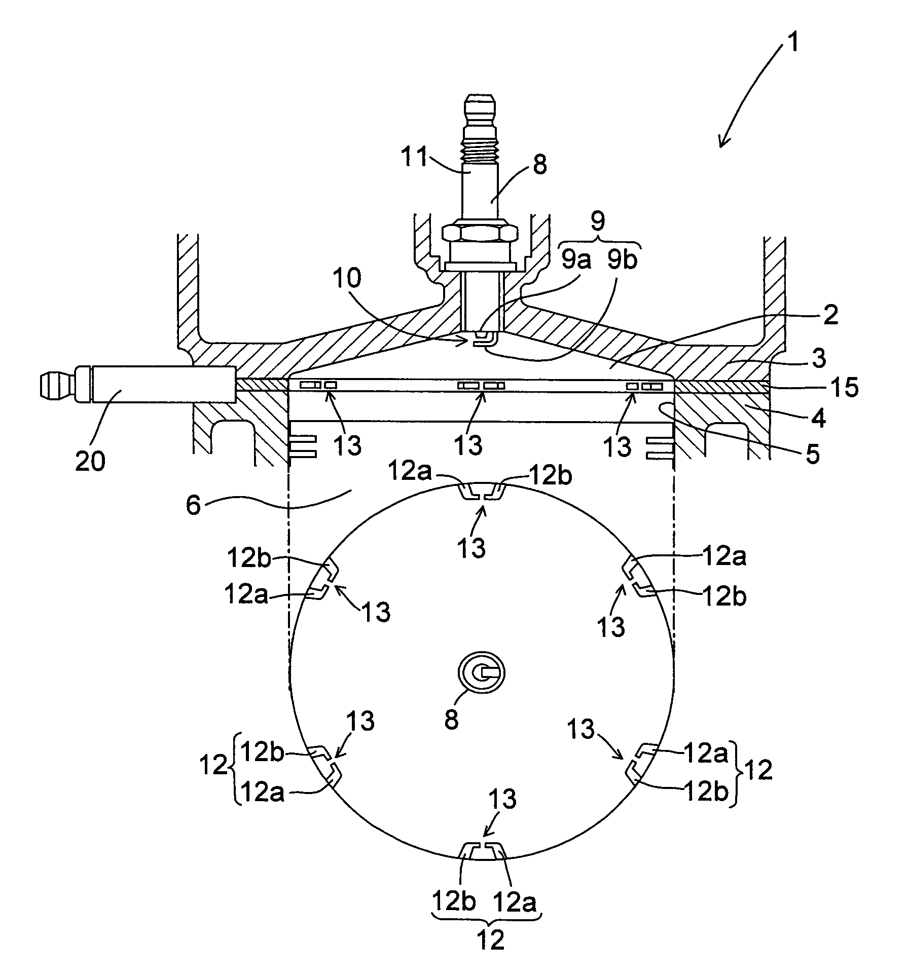
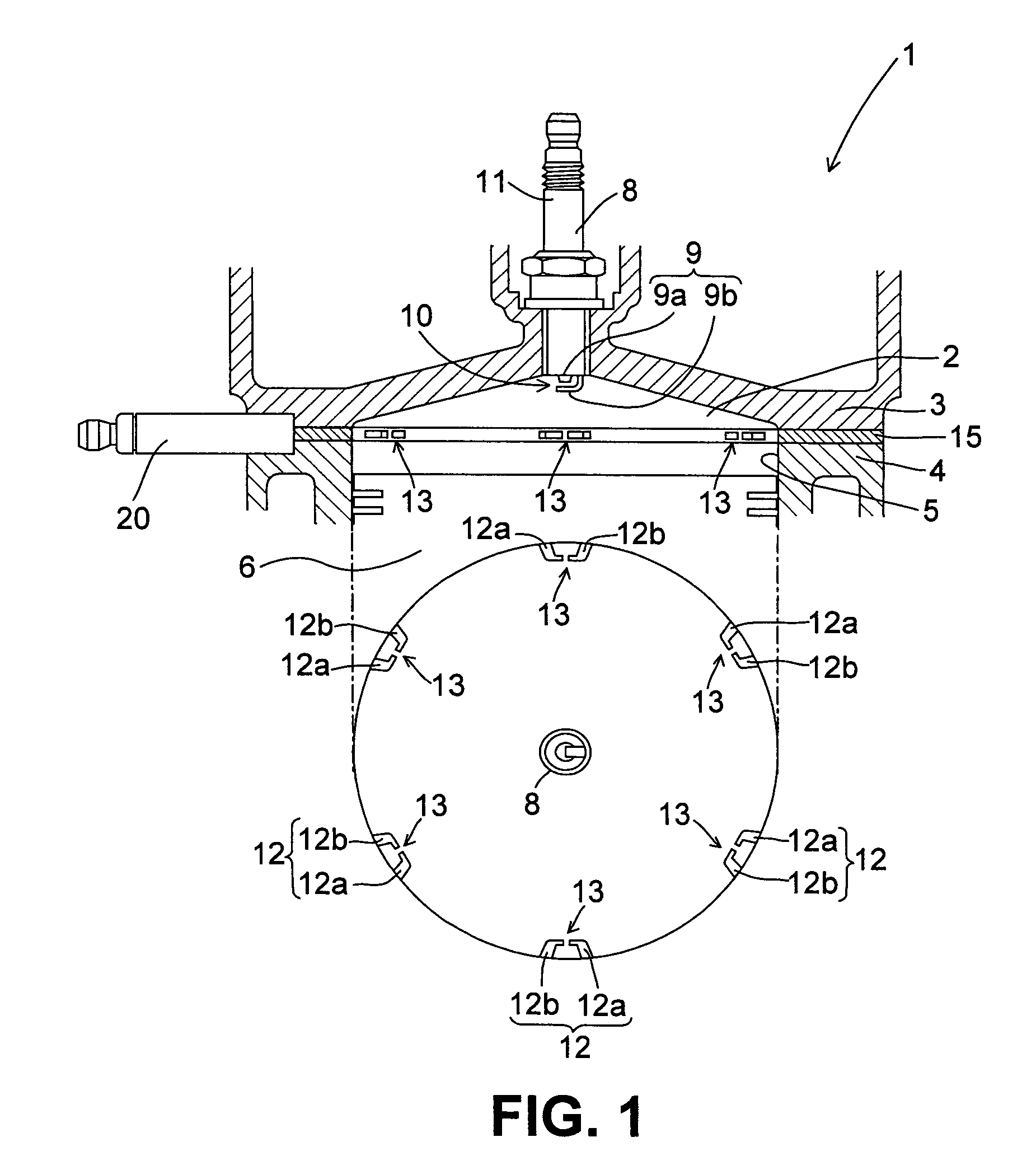
[0036]FIG. 1 shows the schematic constitution of a multipoint ignition engine 1 according to this invention.
[0037]In this embodiment, an engine 1 is a premix engine in which fuel injected through an injector attached to an intake port, not shown in the drawing, is mixed evenly with air, whereupon the air-fuel mixture is introduced into a combustion chamber 2, ignited by spark ignition, and burned. To obtain a desired air-fuel ratio, an intake air amount and the amount of fuel injected by the injector are adjusted. As will be described below, the engine 1 may be a direct injection engine. To improve the fuel efficiency, the air-fuel ratio of the air-fuel mixture is set higher than the stoichiometric air-fuel ratio (at an excess air ratio of approximately 2, for example), but to ensure the output of the engine 1, the air-fuel ratio of the air-fuel mixture may be set equal to or smaller (richer) than the stoichiometric air-fuel ratio depending on the operating region or in the entire o...
second embodiment
[0076]To further improve the output and fuel efficiency of the multipoint ignition engine 1 described above, the compression ratio of the engine 1 may be raised by reducing the thickness of the head gasket 15. As the compression ratio rises, the thermal efficiency improves, leading to improvements in output and fuel efficiency. However, when the thickness of the head gasket 15 is reduced, the distance between the peripheral spark gap 13 and the cylinder head 3 and so on decreases, leading to an increase in the possibility of leakage. Leakage occurs particularly frequently when the thickness of the head gasket 15 is set at 6 mm or less. This applies similarly when the capacitance of the ignition coil is increased.
[0077]In the second embodiment, as shown in FIGS. 7 and 8, leakage from the peripheral spark gaps 13 to the cylinder head 3 and the crown surface of the piston 6 is suppressed by forming leakage-preventing indentations 23, 24 respectively in positions corresponding to the ci...
third embodiment
[0080]To suppress leakage from the peripheral spark gaps 13 into the cylinder head 3 and so on, the third embodiment differs from the first embodiment in the structure of the peripheral electrode pair 12. All other structures are identical to the first embodiment.
[0081]FIG. 11 shows the structure of the peripheral electrode pair 12 according to the third embodiment. The part of the peripheral electrode pair 12 that is exposed to the interior of the combustion chamber 2 takes a linear rod form and does not have a curved portion midway. Further, the peripheral spark gap 13 is formed by causing the tip end surface of one of the electrodes (the earth electrode 12b) constituting the peripheral electrode pair 12 to face the tip end-side side face of the other electrode (the conducting electrode 12a), with a gap therebetween. The angle formed by the exposed parts of the electrodes 12a, 12b is substantially 90°.
[0082]With this structure, the likelihood of leakage from a midway point on the ...
PUM
 Abstract
Description
Claims
Application Information
 - R&D
- Intellectual Property
- Life Sciences
- Materials
- Tech Scout
- Unparalleled Data Quality
- Higher Quality Content
- 60% Fewer Hallucinations
Browse by: Latest US Patents, China's latest patents, Technical Efficacy Thesaurus, Application Domain, Technology Topic, Popular Technical Reports.
© 2025 PatSnap. All rights reserved.Legal|Privacy policy|Modern Slavery Act Transparency Statement|Sitemap|About US| Contact US: help@patsnap.com


