
Medical needle and cutting tool

a cutting tool and needle technology, applied in the field of medical needles or cutting tools, can solve the problems of difficult bending properties, inability to solve complex management of work procedures or the environment, and inability to improve bending strength, so as to reduce resistance, reduce resistance, and prevent bending strong

Inactive Publication Date: 2010-02-16
MATSUTANI SEISAKUSHO CO LTD
View PDF10 Cites 3 Cited by
  • Summary
  • Abstract
  • Description
  • Claims
  • Application Information

AI Technical Summary

Benefits of technology

The solution provides high hardness and resistance to bending, reduces tissue piercing resistance, and minimizes illumination reflection during surgeries, enhancing the tool's durability and usability while preventing rust and adverse tissue reactions.

Problems solved by technology

When the medical needle or the cutting tool is configured by fiber shape structure of the austenite stainless steel, it is superior to any that is configured by any other stainless steel with regards to the difficult bending property due to high toughness, but is inferior with regards to the bending strength.
In this case, the working conditions of the working rate and the like until the hardness necessary for the medical needle or the cutting tool is obtained must be strictly managed, cool working with extremely high precision must be performed, and the management of the work procedures or the management of the environment becomes complex.
In the technique of JP-A No. 9-268354, on the other hand, the hardness may be increased by forming the carburized layer on the surface of the product, but when applied to the product of long rod shape where the bending force is acted, the problem of difficult bending property cannot be solved.
In surgery under such scope, the illumination irradiating the operating field is reflected by the medical needle or the cutting tool, thereby giving great fatigue to the physicians.

Method used


Image

  • Medical needle and cutting tool
  • Medical needle and cutting tool
  • Medical needle and cutting tool

Examples


embodiment 1

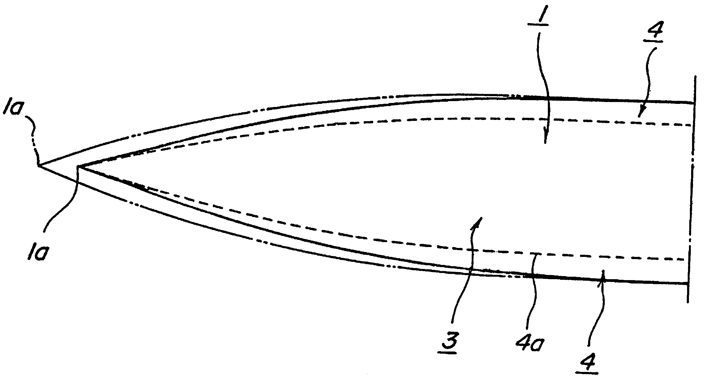
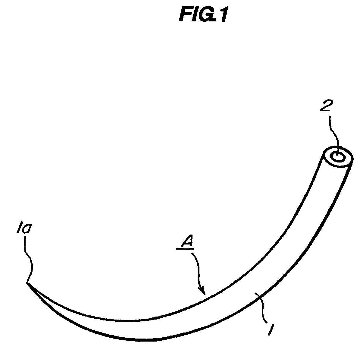
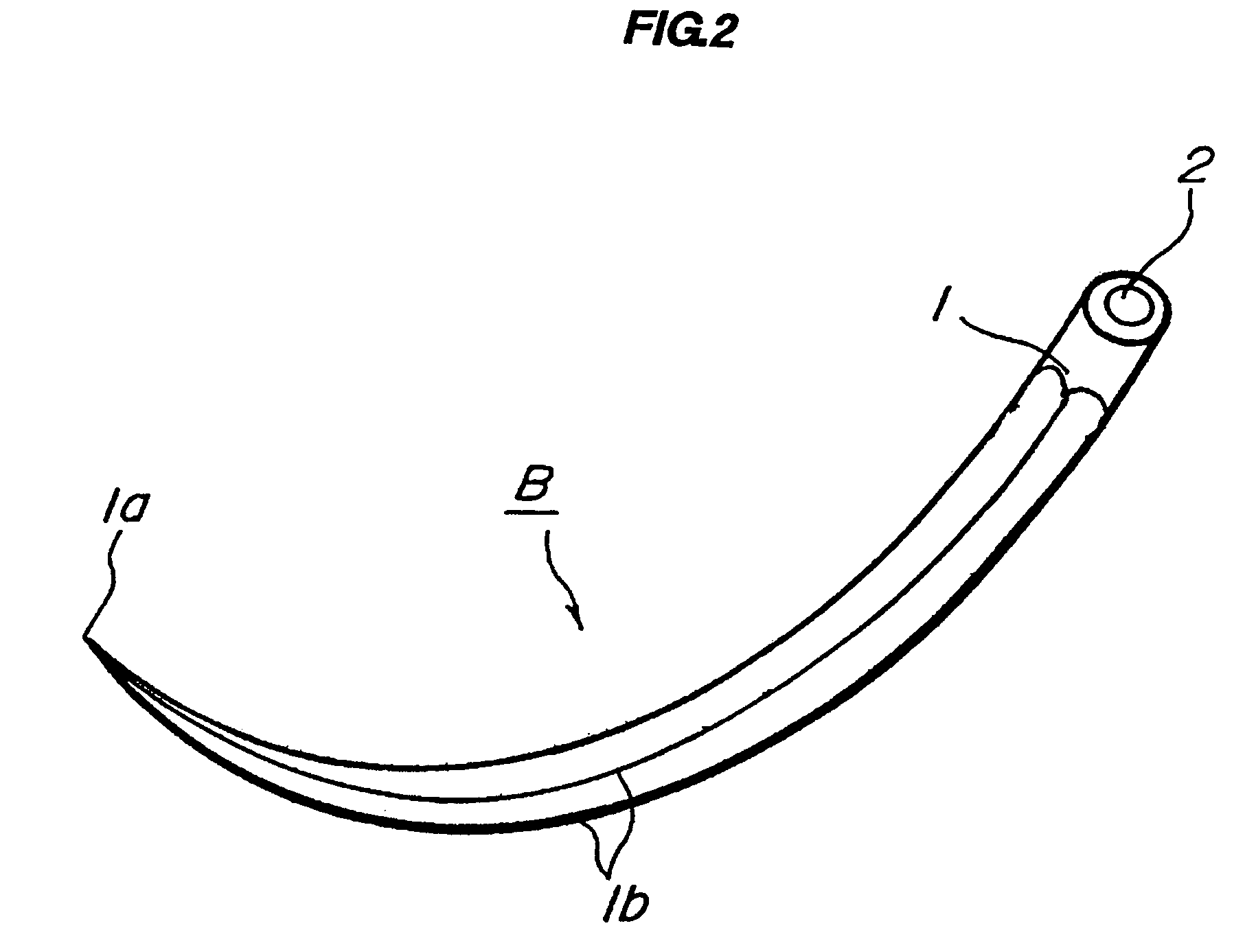
[0051]The first embodiment of the medical needle and the like will now be explained using the figures. FIG. 1 is a view explaining an example of a suture needle serving as the medical needle and the like. FIG. 2 is a view explaining another example of the suture needle serving as the medical needle and the like. FIG. 3 is a view explaining an example of a fiber shape structure obtained through cool pulling work of the austenite stainless steel. FIG. 4 is a view explaining a preferred example of the distal end portion of the suture needle.

[0052]In the present embodiment, the medical needle and the like is formed as a suture needle A shown in FIG. 1 and suture needle B shown in FIG. 2. The suture needle A has the cross section of the body part 1 formed into a circular shape, a sharp needle point 1a is formed at the distal end, and a hole 2 through which the suture thread (not shown) is inserted and bonded is formed at the rear end face. The suture needle A pierces the body tissue with...

embodiment 2

[0063]A second embodiment of the medical needle and the like will now be described with reference to the figures. FIG. 5 is a view explaining an example of a knife serving as the medical needle and the like. FIG. 6 is a view explaining another example of a knife serving as the medical needle and the like.

[0064]The knife C shown in FIG. 5 has a blade part 10 and a shank 11 continuously formed on the blade part 10. The distal end of the knife C is formed as a sharp point 12, and a cutting blade 13 is formed along the outer edges of both sides of the blade part 10 from the point 12. The dark layer 14 is formed on the surface of the knife C, and non-reflectivity is provided by the dark layer 14.

[0065]The knife D shown in FIG. 6 differs from the knife C in that the distal end portion is formed into a curved shape, but other configurations are configured the same way as the above described knife C.

[0066]In knife C, D, the material used is the austenite stainless steel, which material may ...

embodiment 3

[0071]The third embodiment of the medical needle and the like will now be explained using the figures. FIG. 7 is a view explaining an example of a Pesso reamer that is a dental treatment instrument serving as the medical needle and the like. The Pesso reamer E shown in the figure is an instrument for grinding a layer having slightly high hardness such as an ivory or calcified root canal wall formed on the surface of the teeth, and is operated by being mounted on a rotating drive device called a hand piece.

[0072]The Pesso reamer E is configured by including a cutting blade part 21 formed on one end side, a shank 22 formed on the other end side and grasped by a chuck of the hand piece, and a neck part 23 formed between the cutting blade part 21 and the shank 22. The neck part 23 has a function of serving as a fuse that breaks with a twisting force and / or a bending force acting on the Pesso reamer E when some kind of problem occurs in scraping the teeth.

[0073]The cutting blade part 21 ...


PUM

PropertyMeasurementUnit
thicknessaaaaaaaaaa
depthaaaaaaaaaa
thicknessaaaaaaaaaa

Abstract

A medical needle and the like that has small resistance when piercing, scraping or incising the body tissue, that is not easily bent and that reduces the reflection of the illumination as much as possible when in surgery performed under scope is provided. The medical needle and the like has a hardened layer, in which a carbon atom is penetrated, of a depth of 5 micrometers to 70 micrometers provided on a parent material surface of a fiber shape structure having an austenite stainless steel containing 1% to 6% of molybdenum or 13% to 25% of chromium. Further, after the hardened layer is provided, one part of the hardened layer is removed. Further, the dark layer is formed on the outer most surface of the hardened layer to provide a non-reflective surface.

Description

BACKGROUND OF THE INVENTION[0001]The present invention relates to a medical needle or a cutting tool that does not produce rust and that provides high hardness as well as difficult bending property, and that further has non-reflectivity.[0002]The medical needle includes, a suture needle used for suturing the affected area that has been incised or a needle used for blood drawing or fluid infusion, a reamer or a file used for performing root canal forming in dental treatment and the like. The medical cutting tool includes a surgical knife or a knife used when incising the affected area. Thus, the medical needle and the cutting tool have suitable shape in accordance with the intended use.[0003]All of the above mentioned medical needle and the cutting tool have a function of piercing directly through the body tissue and passing the suture thread, or a function of scraping the structure of the teeth or a function of incising the body tissue. In such medical needle or the cutting tool, a ...

Claims


Application Information

Patent Timeline
Patent Type & Authority Patents(United States)
IPC IPC(8): A61B17/06
CPCA61B17/06066A61C5/42A61B2017/00526A61B17/3211
Inventor MASHIKO, MASAKIMATSUTANI, KANJI
Owner MATSUTANI SEISAKUSHO CO LTD
Learn More