High pressure discharge lamp operation method, operation device, light source device, and projection type image display device
a high-pressure discharge and lamp technology, applied in the direction of electric variable regulation, process and machine control, instruments, etc., can solve the problems of reducing the lamp voltage, shortening the distance between the electrodes, and reducing the illumination, so as to suppress the optical output and shorten the life. , the effect of suppressing the optical outpu
- Summary
- Abstract
- Description
- Claims
- Application Information
AI Technical Summary
Benefits of technology
Problems solved by technology
Method used
Image
Examples
first embodiment
[0056]The present embodiment describes a lamp provided in a lamp unit, and a lighting method and lighting apparatus for the lamp.
[0057]In the present embodiment, a lamp unit using a high-pressure mercury lamp in accordance with the present invention is described with reference to drawings.
1. Structure of Lamp Unit
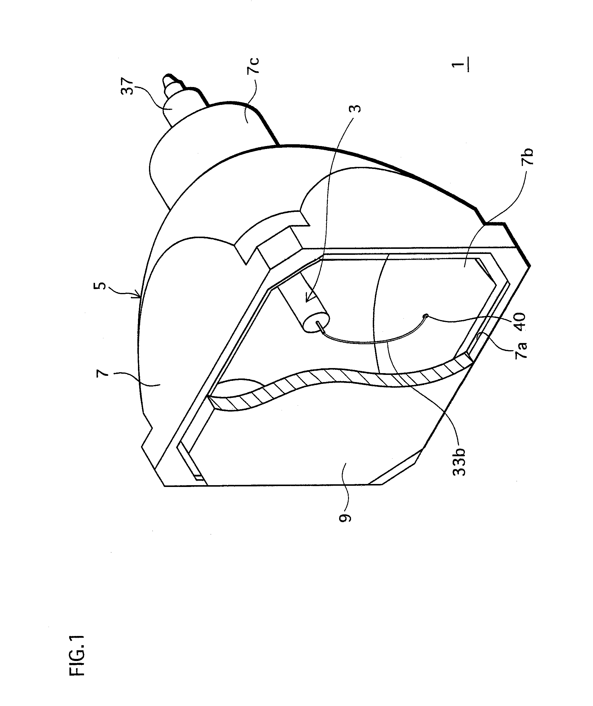
[0058]FIG. 1 is a perspective view of the lamp unit in the present embodiment.
[0059]The lamp unit 1, as shown in FIG. 1, includes a high-pressure mercury lamp (hereinafter, simply referred to as “lamp”) 3 and a reflecting mirror 5, where the lamp 3 is built in the reflecting mirror 5.
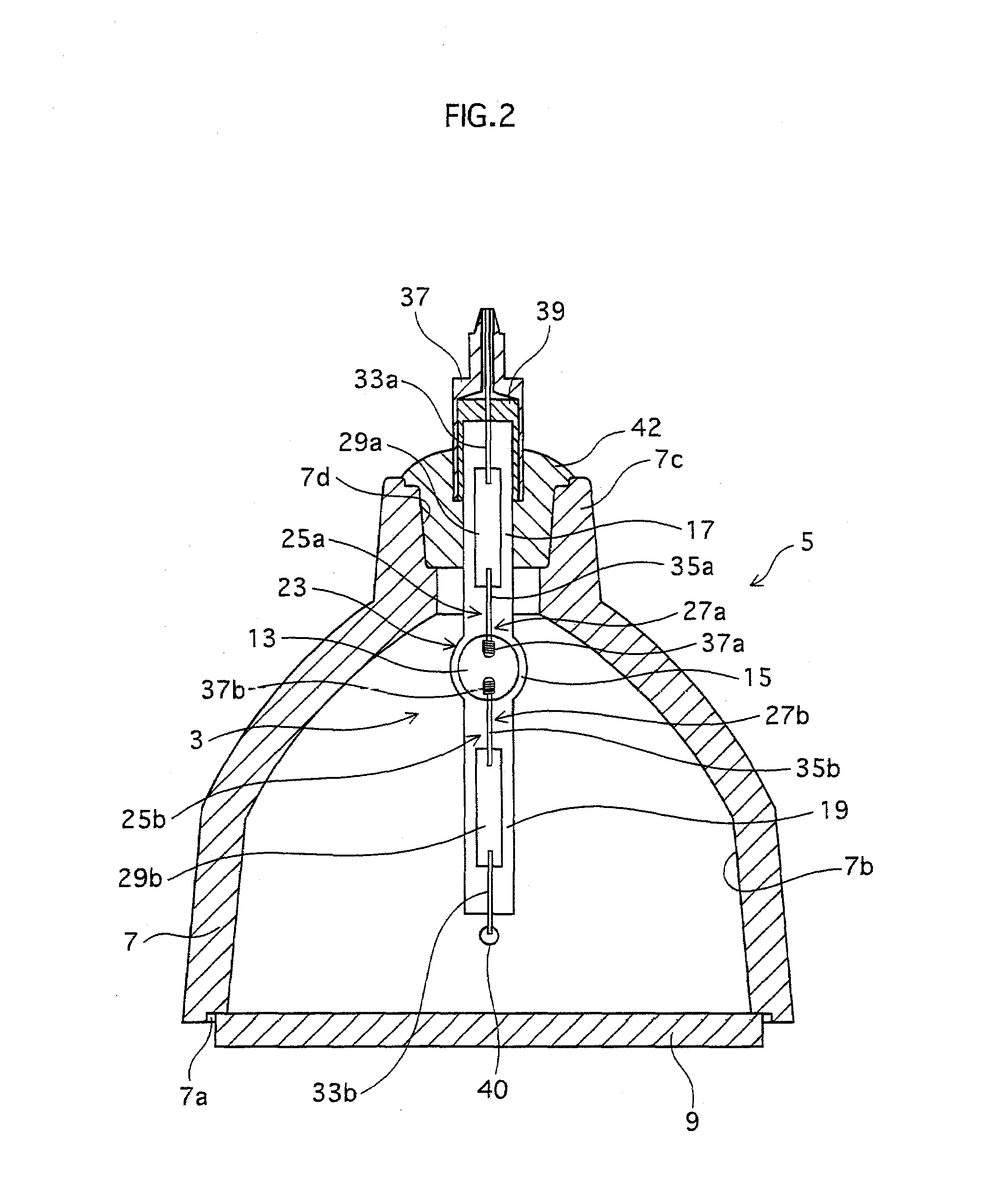
[0060]FIG. 2 is a plan view of the lamp unit, where the reflecting mirror is cut away so as to provide a clear view of an inner structure of the lamp.
1-1. Structure of Lamp
[0061]As shown in FIG. 2, the lamp 3 includes a discharge vessel 23 which has a discharge space 13 therein and electrode assemblies 25a and 25b. The electrode assemblies 25a and 25b are hermetically sealed with two sealing pa...
embodiment
4. Embodiment
4-1. Lamp
[0099]Here, the lamp 3 is considered to be used as, for instance, a projection-type image display apparatus and the like, and thus will be described accordingly. The lamp 3 is a so-called “short arc” type lamp, where a gap (a distance between the electrodes) is set in a range of 0.5 mm to 2.0 mm in order to make the lamp closer to a point source of light.
4-2. DC / DC Converter
[0100]FIG. 6 is a circuit diagram of the DC / DC converter.
[0101]The DC / DC converter 54 includes, for example, an inductor L0, a switching element Q0, a diode D0, and a smoothing capacitor C0. In other words, the DC / DC converter 54 is a publicly known step-down converter. Note that as the switching element Q0, for example, an N-type field-effect transistor is used.
[0102]The switching element Q0 adjusts a current outputted to the DC / AC inverter 55 by switching ON / OFF based on the power setting signal. That is to say, the power setting signal is a pulse signal for the switching element Q1 to swi...
second embodiment
[0119]In the first embodiment, a description was made on the lamp unit and the lighting apparatus which lights the lamp attached to the lamp unit.
[0120]In the second embodiment, a description will be made on a DLP (registered trademark) front-projection type image display apparatus which includes the lamp unit and the lighting apparatus described in the first embodiment.
[0121]FIG. 10 is an overall diagram of the front-projection type image display apparatus, where part is cut away to provide an inner view of the lamp, in the second embodiment.
[0122]A front-projection type image display apparatus (hereinafter, referred to as “projector”) 100 is a DLP (registered trademark) type apparatus with a single DMD (registered trademark) chip.
[0123]As shown in FIG. 10, the projector 100 is constituted from a power unit 102 including the above-mentioned lighting apparatus, the above-mentioned lamp unit 1, an image unit 104 which performs an optical system and image processing, a control unit 10...
PUM
 Abstract
Description
Claims
Application Information
 - R&D
- Intellectual Property
- Life Sciences
- Materials
- Tech Scout
- Unparalleled Data Quality
- Higher Quality Content
- 60% Fewer Hallucinations
Browse by: Latest US Patents, China's latest patents, Technical Efficacy Thesaurus, Application Domain, Technology Topic, Popular Technical Reports.
© 2025 PatSnap. All rights reserved.Legal|Privacy policy|Modern Slavery Act Transparency Statement|Sitemap|About US| Contact US: help@patsnap.com


